
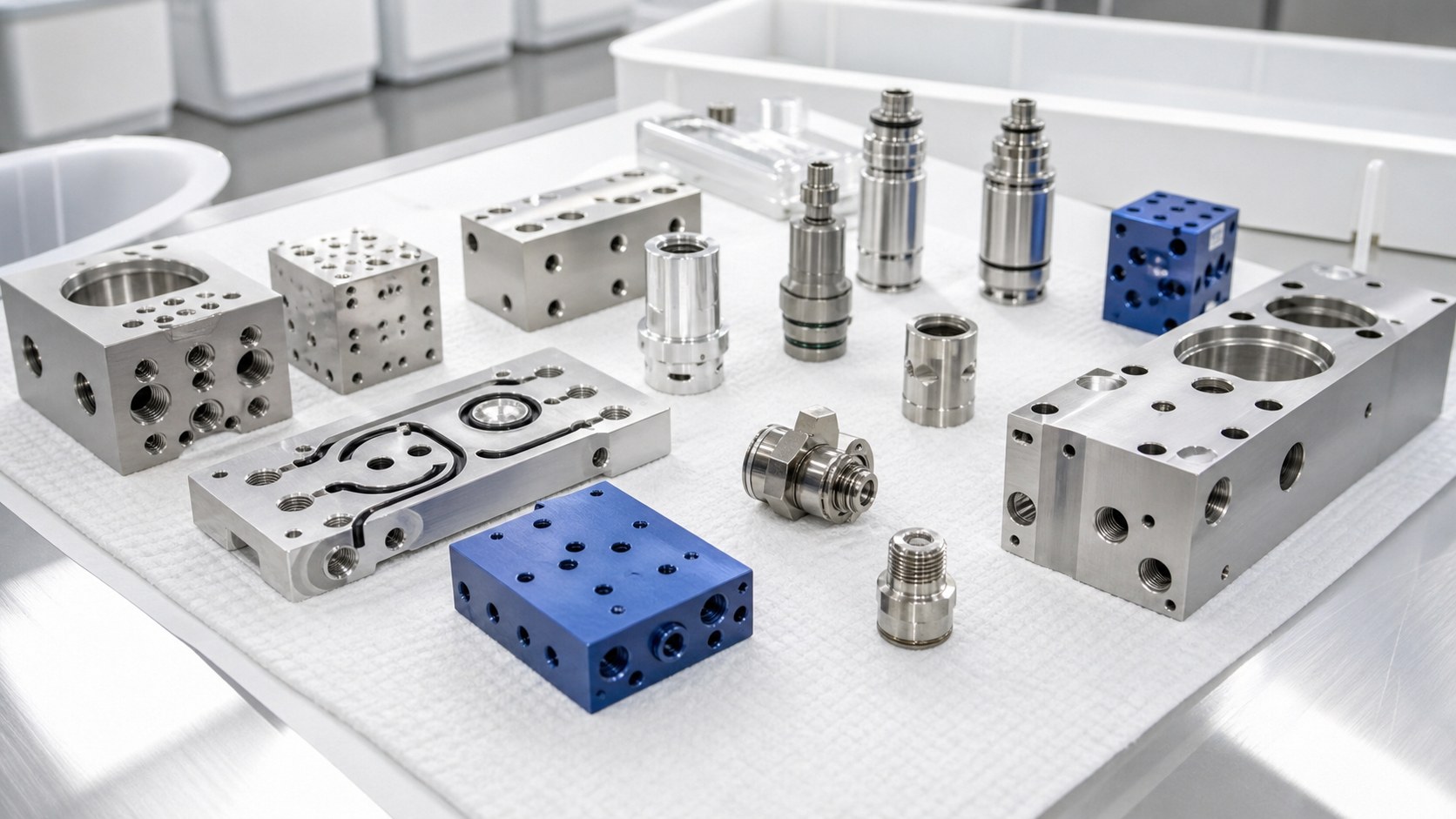
Leak-Testable Sealing Interfaces in CNC-Machined Medical Fluid Manifolds
Why the interface matters
A medical fluid-control manifold is more than a block with drilled passages. The part must guide fluid through the intended route while allowing valves, fittings and seals to seat consistently. Small errors at an O-ring groove, port intersection or mounting face can change compression, trap residue or create a leak path. The manufacturer therefore needs a drawing that separates fluid-contact features from simple locating features and identifies which surfaces become the sealing datums. The goal of this guide is to make the mechanical handoff between device designer and machine shop easier to review.

Start with the fluid path
Before selecting cutters, trace the intended flow path from inlet to outlet on the 3D model and 2D drawing. Mark blind ends, intersecting bores, valve seats and any channel that will be closed by a cover or diaphragm. Confirm the port thread or tube fitting standard, its engagement depth and the available wall thickness. A cross-drilled intersection should have a defined edge condition rather than an ambiguous instruction to deburr all edges. If the assembly contains a disposable fluid set, clarify whether the manifold itself is inside the wetted path; that decision changes the material, surface, cleaning and validation discussions.
Choose material for the actual use
316L stainless steel is a common candidate where corrosion resistance and robust threaded features matter. Engineering polymers may make sense for weight, electrical isolation or complex fluid routing, but chemical compatibility and sterilization exposure must be checked against the final device design. Material choice should be made with the device team, not inferred from a stock photo or a generic machining rule. Ask for the exact material grade, stock condition, applicable certificate and any passivation or surface treatment requirement. Where a change of material is proposed, repeat the sealing and compatibility review rather than carrying over assumptions from the previous revision.
Design the sealing land
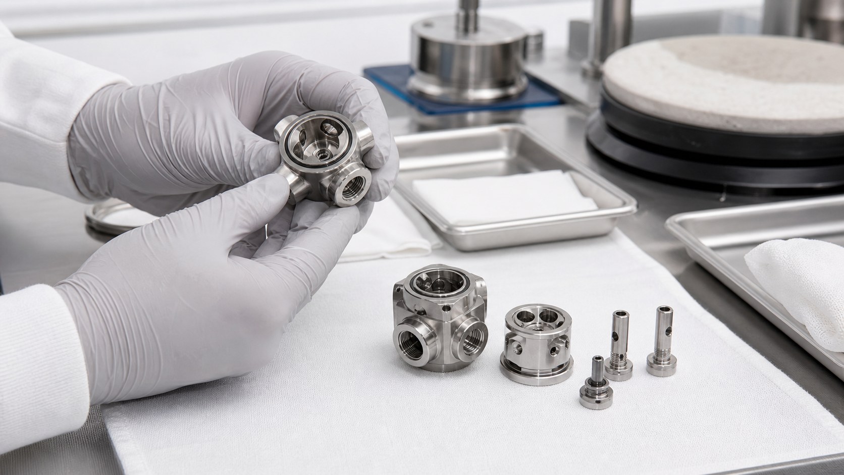
An O-ring seal depends on groove width, depth, corner radii and the flatness of the surrounding land. The drawing should specify the gasket or O-ring size and the compression target defined by the designer, then identify the surfaces that control that compression. A nominally smooth face can still leak if clamping warps a thin cover or if a groove breaks into a nearby drilled port. Avoid placing a sharp cross-hole break in the contact band. Make space for lead-ins that protect elastomer edges during assembly, and specify surface finish only where it has a functional reason and a suitable measurement method.
Plan the CNC sequence
A stable process normally establishes a primary face and side datum, roughs the bulk features, then finishes sealing and port features from controlled setups. On a small valve block, a fixture must hold the part without distorting thin walls or covering an inspection surface. Tool paths for grooves and seats should limit chatter and avoid leaving a raised lip at the cutter exit. Deep or intersecting bores need suitable chip evacuation; the final cleaning plan cannot compensate for a trapped burr that was never removed. If a five-axis setup reduces datum transfer, document which critical features are still checked after the part is unclamped.
Control burrs without damaging edges
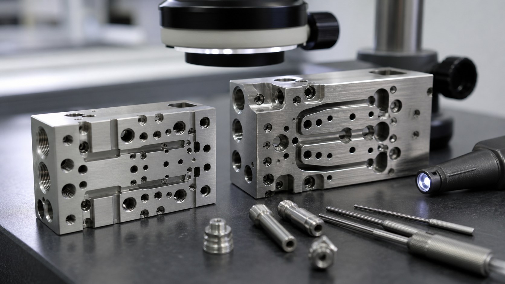
Cross-drilled passages are difficult because the burr may sit inside an inaccessible junction. The machinist can adjust tool geometry, feed, sequence and break-through direction to reduce burr formation, then use a validated secondary removal method. Aggressive brushing can round a valve seat or push debris farther into a port. Establish a specific acceptance criterion for each fluid-contact edge and inspect with borescope or suitable optical equipment when direct viewing is impossible. The drawing should distinguish a protective edge break from a seal land that must remain intact.
Inspect the right dimensions
Measure the features that govern assembly and sealing: port position relative to the mounting datum, groove depth and width, face flatness, bore size, seat geometry and thread quality. A coordinate measuring machine can establish geometric relationships, while optical tools may be better for tiny groove and intersection features. Record the method, fixture condition and sampling plan alongside the results. If a feature cannot be measured reliably after assembly, inspect it before the cover is installed. Keep inspection records tied to the material lot and drawing revision so a later deviation can be traced to the right process state.
Leak testing is a system decision
A machined manifold is often leak-tested with a fixture, but pressure, medium, dwell time, allowable leakage and pass/fail limits come from the device specification. A shop should not invent a universal test value. Define which ports are plugged, which are connected, whether testing occurs before or after valves and seals are fitted, and how the part is dried afterward. A dimensional pass does not prove fluid tightness, and a successful leak test does not replace inspection of a damaged seal land. Both forms of evidence have different roles in the acceptance plan.
Clean, protect and document
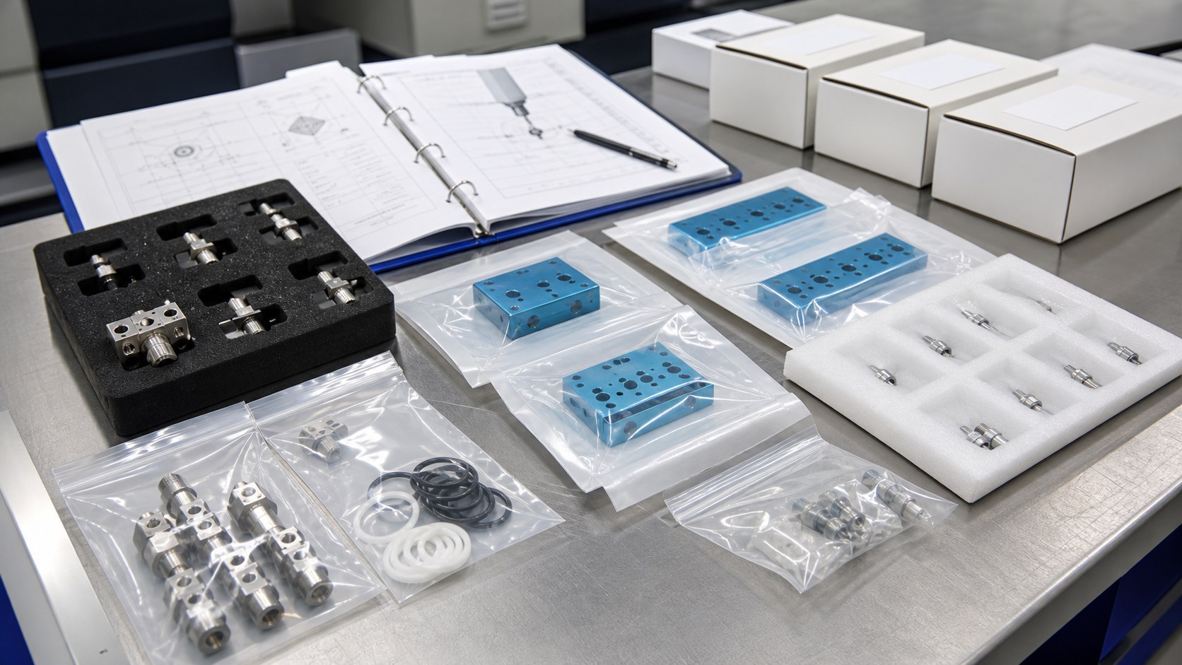
After machining and inspection, select a cleaning process compatible with the material, finishing method and intended device use. Verify that coolant, chips and loose particles have been removed from intersecting passages; protect threads and precision faces during transfer. Package each part so it cannot abrade a sealing land in transit, and identify its revision and lot without putting unsupported sterile claims on the bag. For an RFQ, supply the drawing, model, annual and batch quantities, material specification, seal details, critical dimensions, cleaning level, test protocol and required inspection records. Those inputs make a meaningful process and price review possible.
FAQ
What should be marked critical on the drawing?
Identify seal lands, groove dimensions, port intersections, valve seats, thread requirements and the datums used to locate them. Mark the associated inspection method where visual access is limited.
Is 316L always required?
No. The device designer must choose material based on fluid exposure, mechanical loading, cleaning or sterilization needs and regulatory design controls. 316L is one possible machining choice.
How are hidden cross-hole burrs checked?
Use a defined deburring process and inspect accessible openings optically. For hidden junctions, a borescope or validated cleaning and inspection approach may be needed.
Can a dimensional report replace leak testing?
No. Dimensions and leak performance answer different questions. If leak testing is required, the device team must define test medium, pressure, duration and acceptance limit.
When should the manifold be cleaned?
Cleaning follows burr removal and inspection, with a final check that passages are free of residue. The exact process depends on material and the device's cleanliness specification.
What belongs in a useful RFQ?
Send 2D drawings and 3D models, revision, material and lot documentation needs, seal design, quantities, critical tolerances, surface and cleaning requirements, plus the leak-test protocol.