
CNC Machining Ophthalmic OCT Components: Optical Base Plates, Lens Holders and Mirror Mounts
Ophthalmic OCT and retinal imaging devices rely on stable optical alignment. The machined structure around the light path may look like ordinary plates and brackets, but it controls lens spacing, mirror angle, detector position, heat dissipation and the repeatability of factory calibration. CNC machining for these medical optical components must therefore combine dimensional precision with surface cleanliness and controlled black finishes.
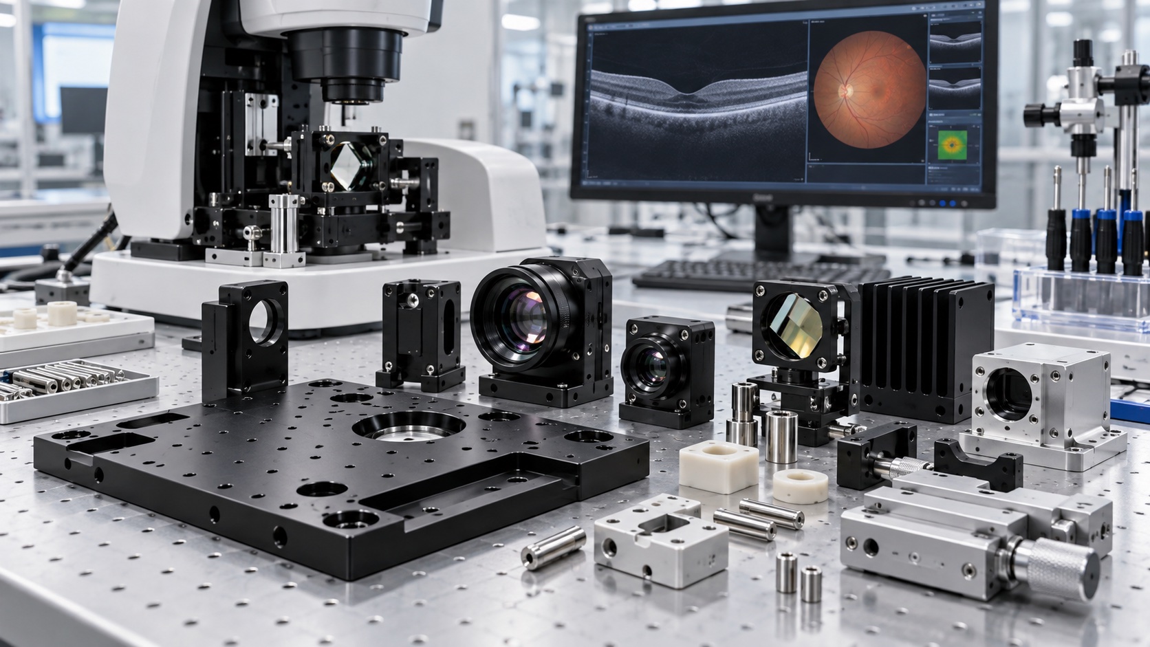
Typical parts include optical base plates, lens barrel holders, galvanometer mirror mounts, detector brackets, heat sink blocks, adjustment sliders and PEEK spacers. 7075-T6 aluminum is often selected for optical benches because it offers high stiffness with lower weight. 6061 aluminum may be used for covers and heat sinks, while stainless pins and inserts provide wear-resistant location points.
Datum strategy should start from the light path. The central optical aperture, dowel pin holes and flat datum pads are more important than outside cosmetic edges. If these features are split across uncontrolled setups, small angular errors can become image drift or focus variation. A better process finishes the aperture, pin bores and datum pads in a planned sequence that reflects the assembly stack.
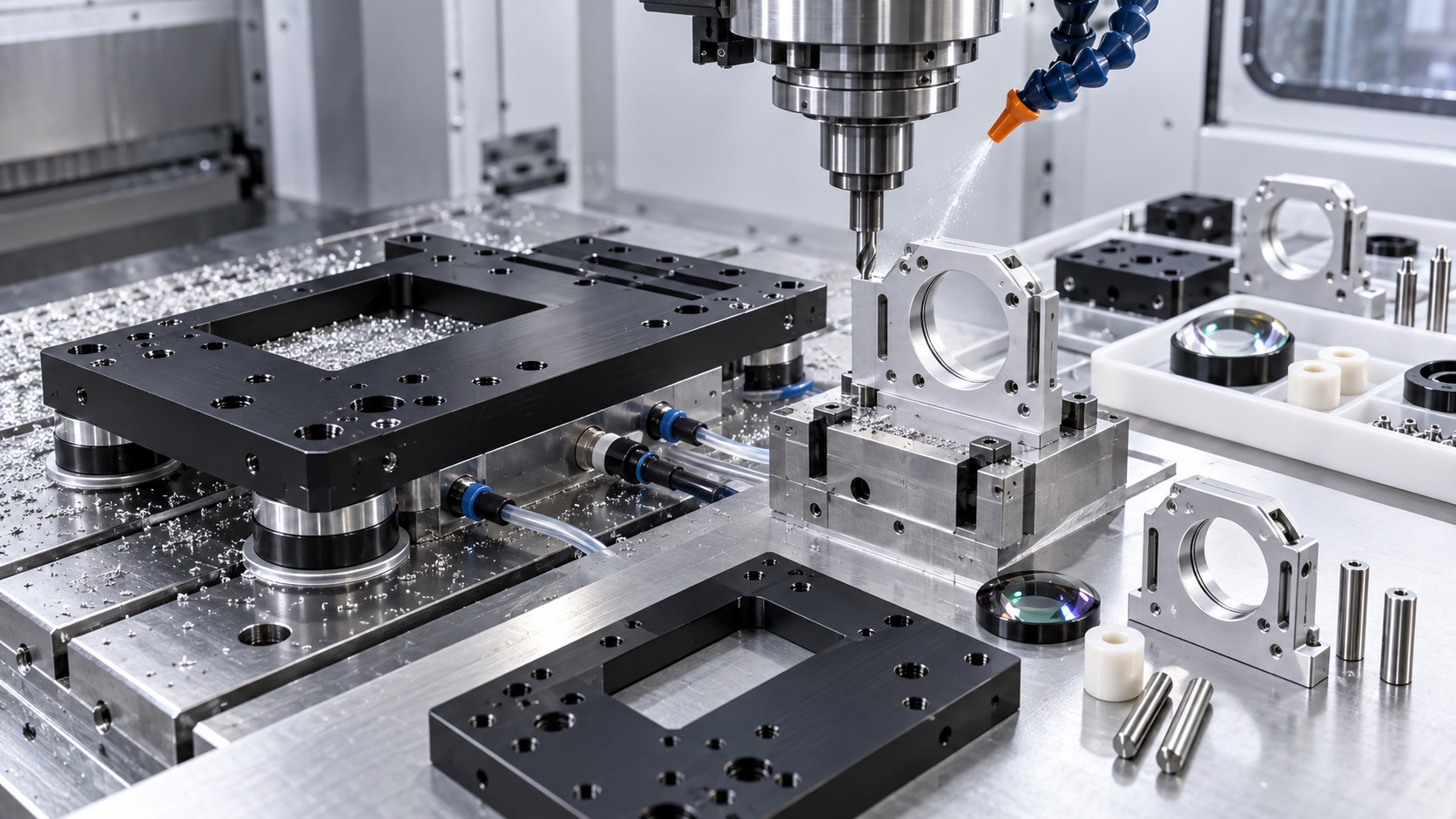
Black anodizing is common because stray reflection must be reduced inside optical equipment. However, anodizing changes surface thickness and may affect tight bores, threaded holes and sliding slots. Critical fits should be masked, post-checked or designed with coating allowance. Exposed datum pads may remain brushed or selectively finished when metal contact is required.
Lens holders and mirror mounts need clean bores, square faces and burr-free edges. A tiny burr near an optical seat can tilt a lens or contaminate a clean optical chamber. Tool choice, climb finishing, careful deburring and controlled washing are as important as the nominal tolerance on the drawing.
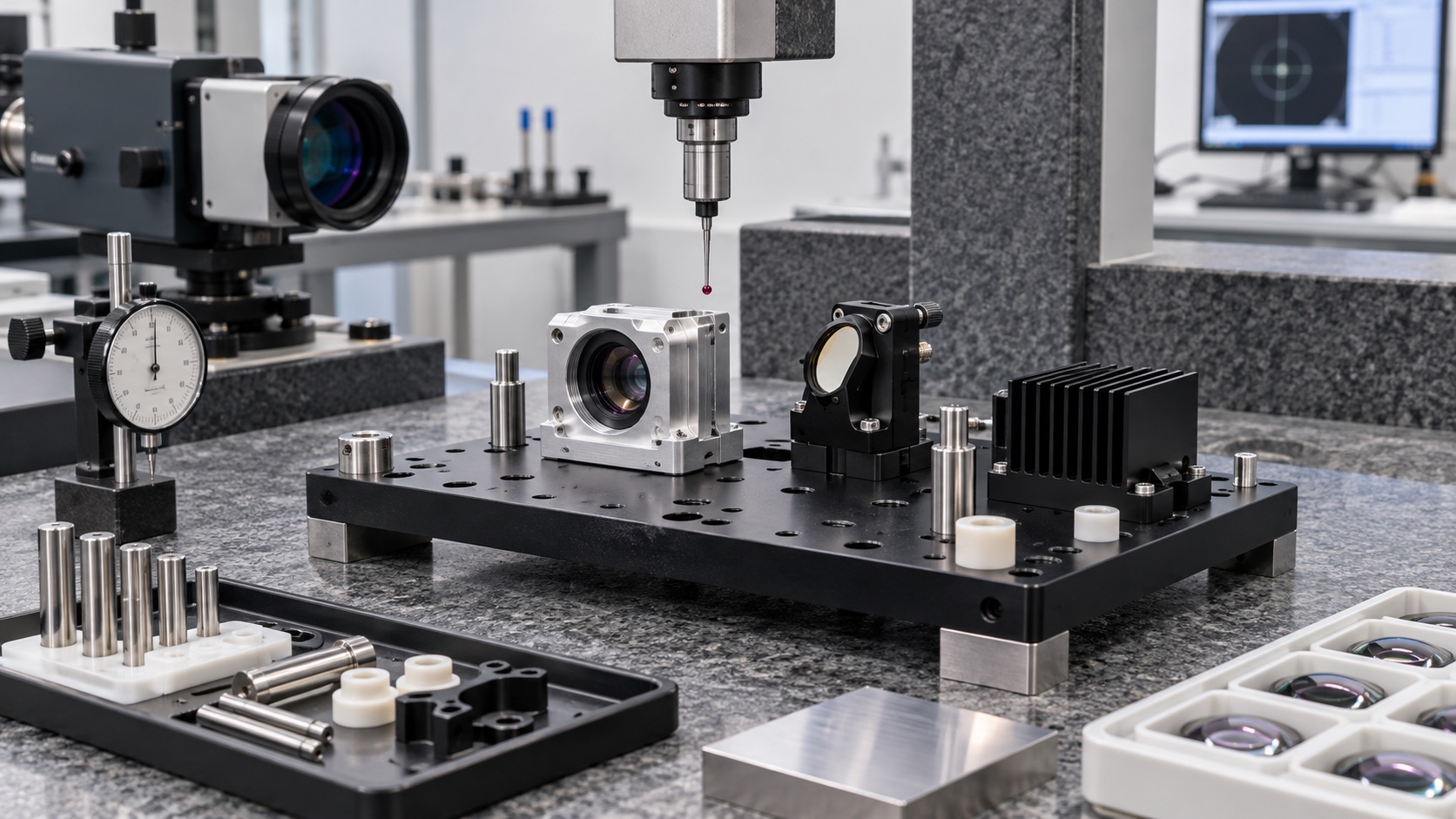
Inspection should combine mechanical and optical thinking. CMM data can confirm hole position, flatness and perpendicularity, while gauge pins and optical alignment checks confirm practical assembly. For heat sink blocks, fin spacing and thermal contact flatness matter. For PEEK spacers, measurement pressure should not deform the material.
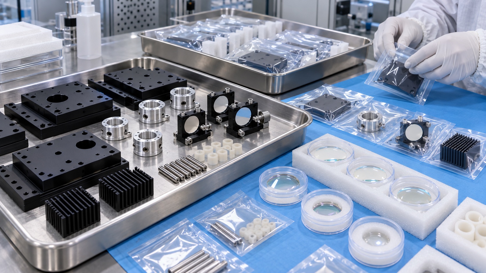
Packaging matters because optical components are sensitive to scratches, dust and mixed-material contact. Black anodized plates, lens holders, pins, PEEK spacers and optical elements should be separated in clean trays or pouches. This helps overseas medical device buyers reduce incoming cleaning and protect calibrated surfaces.
For RFQ review, the supplier should receive 3D models, 2D drawings, coating notes, critical optical datums, annual volume, cleanliness needs and inspection report expectations. Clear input lets the CNC process protect the optical function instead of treating the parts as ordinary aluminum blocks.
FAQ
Which OCT parts are most sensitive to machining error?
Optical apertures, dowel bores, lens seats, mirror mount faces, datum pads and adjustment slots usually drive alignment accuracy.
Why use black anodizing?
Black anodizing reduces stray reflection and gives optical assemblies a stable, wear-resistant surface.
Why choose 7075-T6 for an optical base?
It provides higher stiffness than many aluminum alloys, helping the optical path remain stable.
How are coated holes controlled?
Critical holes are designed with coating allowance, masked when needed and checked after anodizing.
What inspection is useful?
CMM flatness and position reports, gauge pin checks, bore inspection, surface finish review and optical alignment checks are useful.
What should be included in an RFQ?
Send 3D files, 2D drawings, coating notes, optical datum requirements, quantity, cleanliness and inspection needs.
Contact: tanghangyun@oemach.com