
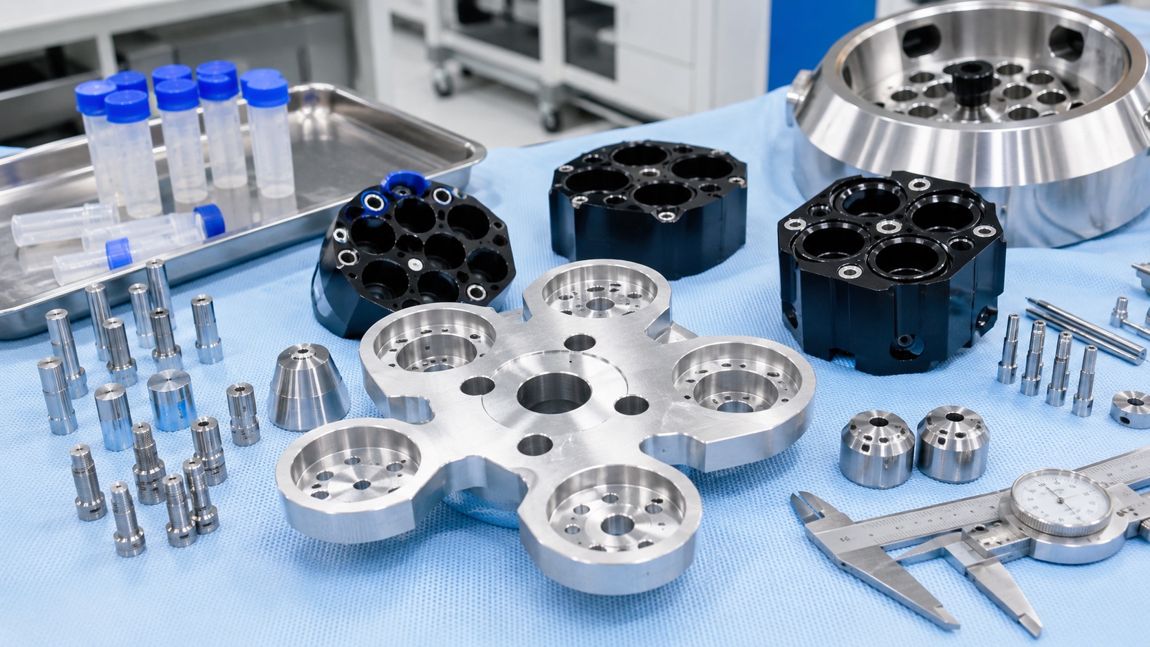
Medical centrifuges look simple from the outside: a motor, a rotor, a lid and a control panel. Inside the rotating system, however, every adapter, carrier and balancing surface must hold geometry under speed, repeated cleaning and frequent loading. CNC machining is a practical way to control those interfaces because it can combine light weight, rigid structure, tight datum relationships and stable batch repeatability in the same component.

Part Families In A Centrifuge Assembly
Typical machined components include rotor adapter plates, sample bucket carriers, tube sleeves, retaining collars, stainless pins, counterweights and balance verification fixtures. A rotor adapter plate may connect the drive hub to different tube layouts. A bucket carrier may support swinging cups or fixed-angle tube positions. A balance fixture helps the equipment maker verify matched sets before final assembly. These parts are not usually implants, but they still belong to the medical equipment supply chain, so the manufacturing plan must emphasize clean handling, traceable material and predictable surface quality.
The most demanding feature is often not a single tolerance on a drawing. It is the relationship between the center bore, radial pockets, dowel holes and mounting counterbores. If the center bore is accurate but the surrounding pattern shifts, the assembly can still create vibration. If a pocket depth varies across the plate, sample height and mass distribution can change. Good CNC planning treats the component as a rotating system, not only as a milled plate.
Material And Fixture Strategy
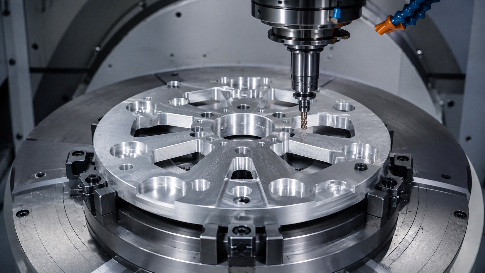
7075-T6 aluminum is often selected for rotor adapters because it provides high strength with relatively low mass. 6061-T6 can be appropriate for covers, brackets or lower-load carriers. Stainless steel is commonly used for pins, shafts, locking posts and wear surfaces. PEEK or other engineering plastics may appear where chemical resistance or insulation is more important than stiffness. The final selection depends on rotational speed, cleaning chemistry, expected life and the equipment maker's validation plan.
Fixture design should reference the future assembly datums. For a rotor adapter plate, the center bore, locating face and dowel pattern normally deserve priority. Soft jaws, vacuum assistance, expanding mandrels or dedicated radial supports can reduce distortion. A common process is rough machining on one side, stress relief or rest time if required, semi-finishing the opposite side, then final boring and circular interpolation after the part has stabilized. This sequence protects flatness and concentricity better than simply finishing every feature in the first setup.
Machining Details That Reduce Risk
Medical centrifuge components often include deep counterbores, lightening pockets, threaded holes, thin webs and chamfered tube interfaces. Sharp transitions can create stress concentration and cleaning difficulty, so controlled radii and burr-free edges are important. Pocketing paths should remove material symmetrically. Tool wear should be monitored because a small change in bore size or surface finish can affect repeated assembly. On visible aluminum surfaces, consistent tool marks and anodizing preparation are also part of the quality result.
For sample bucket carriers, wall thickness and clamping force deserve special attention. Excessive clamping can deform thin walls before final finishing. Insufficient clamping can allow vibration marks or positional drift. For stainless pins, turning and grinding may be combined to control diameter, shoulder squareness and surface finish. Where pins are pressed into aluminum carriers, both components must be toleranced as a pair, not as isolated drawings.
Inspection And Documentation
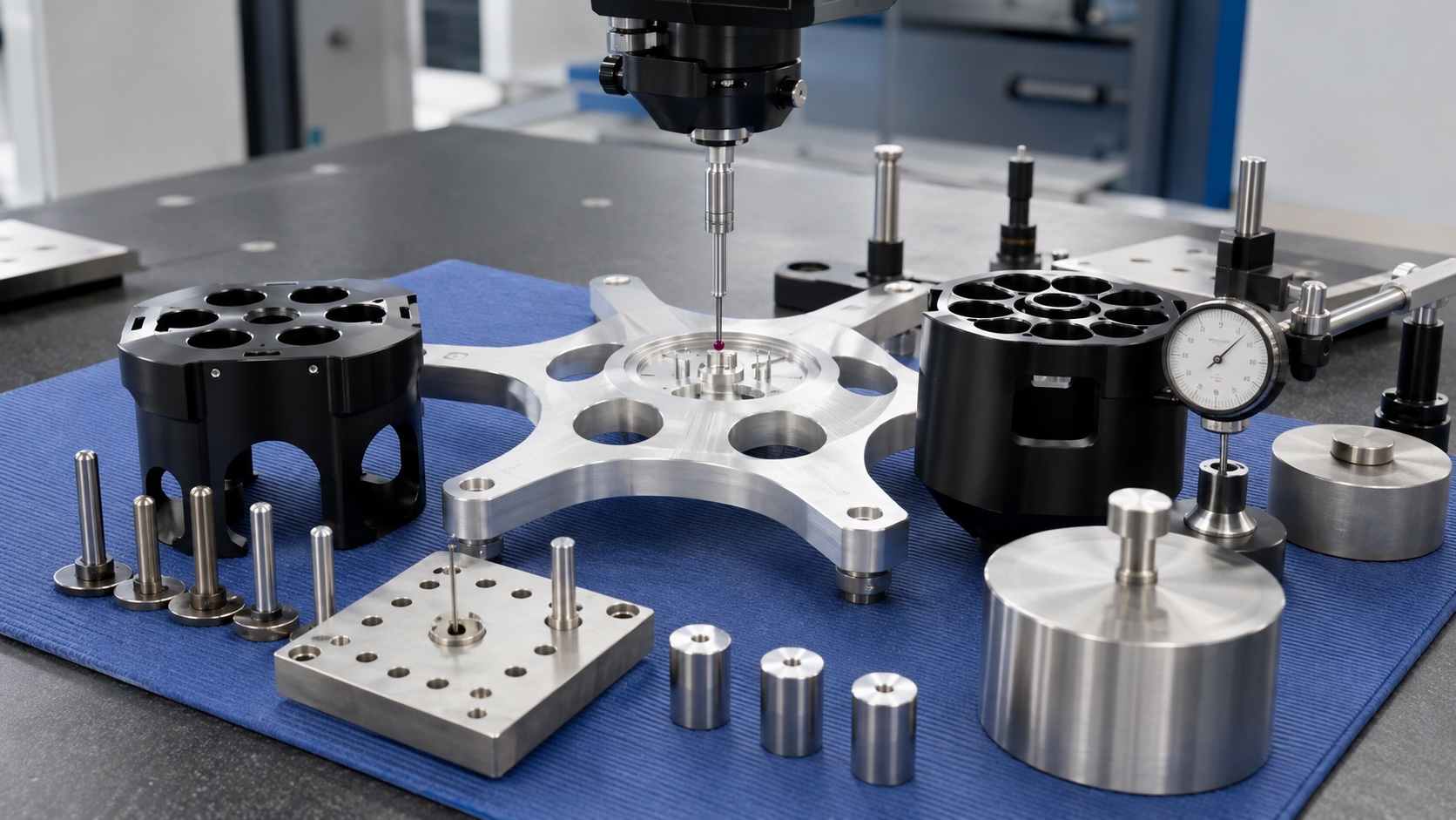
Inspection normally includes CMM checks for hole position, bore size, flatness and pocket depth. Runout can be checked on a rotary fixture or balancing stand. Gauge pins help confirm small locating holes, while surface roughness checks may be required on bearing seats, sample contact surfaces or sealing interfaces. For rotating parts, symmetrical material removal and consistent weight distribution should be reviewed before the lot is released.
Documentation should connect material certificates, heat lot information, machining revision, inspection data, surface treatment batch and packaging record. This is especially useful when a centrifuge manufacturer validates a new rotor configuration or changes a tube format. When the supplier can provide stable measurement data across prototype, pilot and production batches, the equipment maker has fewer variables to manage during assembly and performance testing.
Surface Finish, Cleaning And Packaging
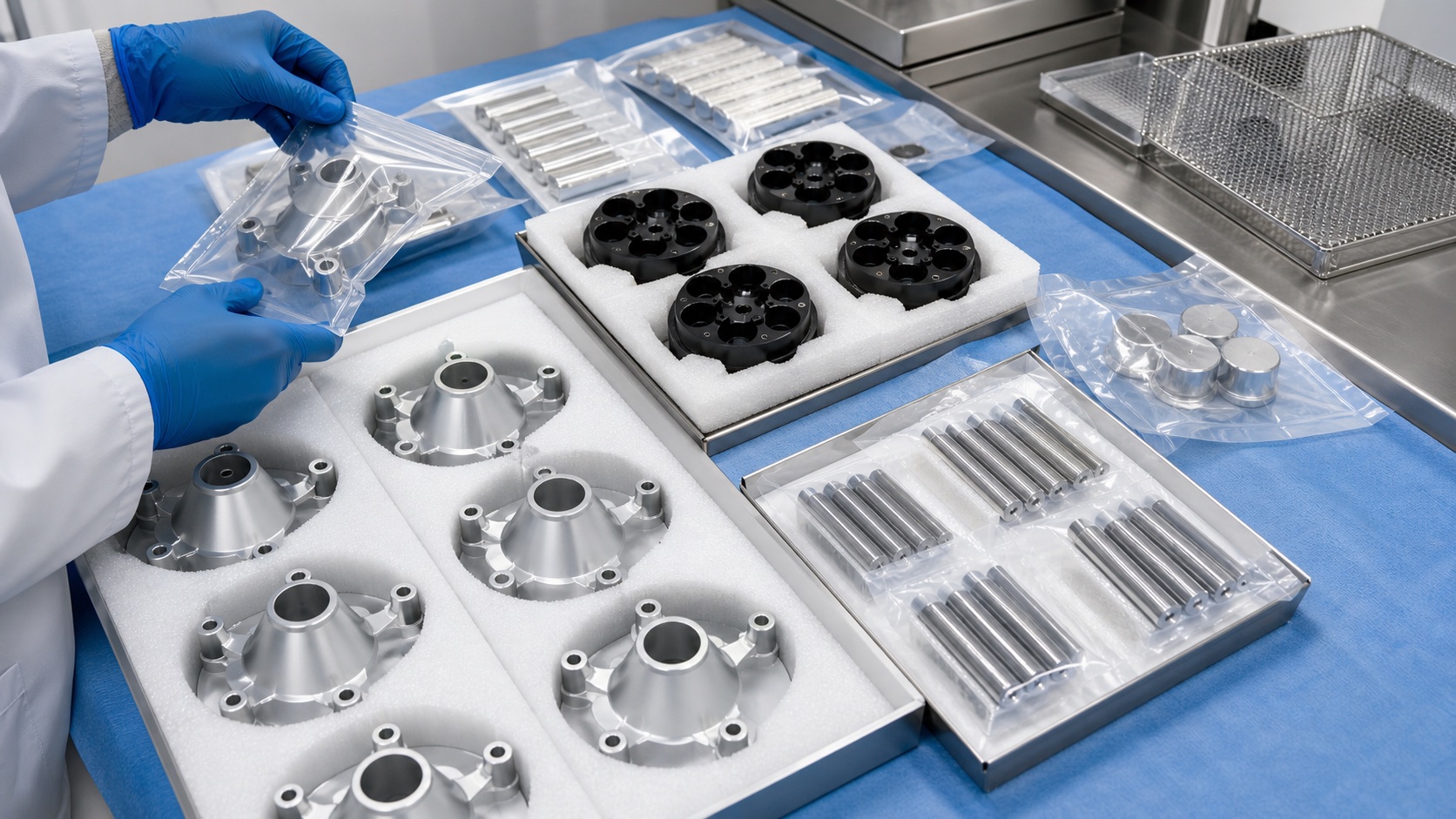
Aluminum rotor adapters can be clear anodized for corrosion resistance or hard anodized for additional wear protection. Critical bores, grounded faces and threaded inserts may need masking. Stainless pins can be passivated after machining. After final inspection, components should be deburred, cleaned, dried and packed so that machined faces do not rub against each other. Foam separators, individual pouches and batch labels help protect both quality and traceability.
Conclusion
CNC machining for medical centrifuge components is less about making a single accurate feature and more about protecting the balance of the whole rotating assembly. A strong process connects material choice, fixture datum strategy, symmetric machining, careful deburring, CMM inspection and clean packaging. For rotor adapters, sample bucket carriers and balance fixtures, this approach supports safer assembly, smoother operation and more predictable production.
FAQ
Which centrifuge parts are most suitable for CNC machining?
Rotor adapters, sample bucket carriers, balance fixtures, retaining rings, pins and inspection masters are all good CNC machining candidates when stable geometry and repeatable alignment are required.
Why is 7075 aluminum often selected for rotor adapter plates?
7075-T6 offers high strength-to-weight ratio and good machinability, helping the adapter remain rigid while reducing rotating mass in laboratory centrifuge assemblies.
What tolerances matter most on a centrifuge rotor adapter?
Concentricity, bore size, flatness, hole position, pocket depth and runout are usually the most important features because they affect rotation, balance and assembly repeatability.
How is balance considered during CNC machining?
Material removal is planned symmetrically, fixtures reference the center bore, and final inspection checks weight distribution, radial pocket consistency and runout before delivery.
Can these components receive anodizing or passivation?
Aluminum components can be clear or hard anodized, while stainless pins and shafts can be passivated; masking plans should protect bearing seats, datum bores and threaded features.
How are medical centrifuge parts packaged after inspection?
Cleaned parts are separated with foam, sealed in clear pouches when needed, protected against surface contact and labeled by batch, revision and inspection status.
Contact: tanghangyun@oemach.com