
CNC Machining Medical Imaging Equipment Parts
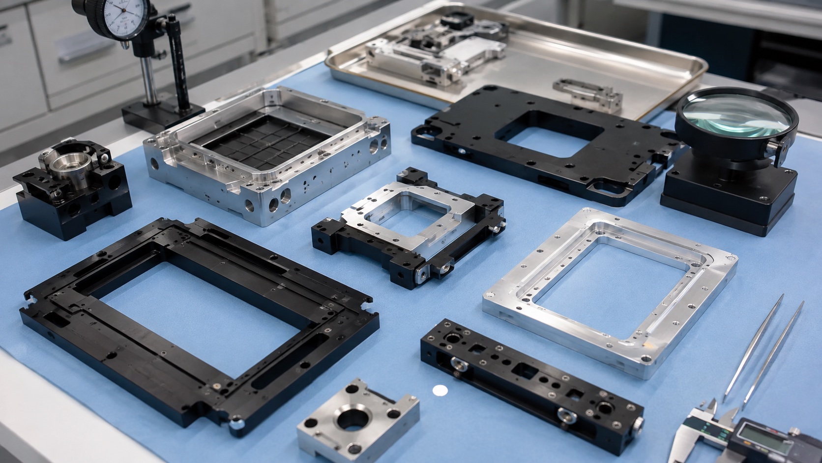
Medical imaging equipment depends on rigid and repeatable mechanical platforms. CT detector frames, X-ray collimator mounts, sensor carrier brackets, optical module plates and shielding adapters must hold position under thermal load, vibration and repeated service access. These parts are not disposable medical items, but their machining quality directly affects detector alignment, calibration stability and assembly efficiency. CNC machining is used because it can produce large windows, thin ribs, counterbores, dowel holes, alignment slots and flat datum surfaces in aluminum or stainless steel with predictable repeatability.
Critical Requirements for Detector and Collimator Parts
The most important requirement is stable geometry. A detector carrier frame may need parallel rails, accurate dowel locations, flat seating surfaces and controlled window size. A collimator mount may need pocket depth, slot width and perpendicularity so that shielding or optical elements sit correctly. Small burrs around counterbores can prevent modules from sitting flat. Distortion after anodizing can also affect assembly. Drawings should mark datum faces, critical hole relationships, coating thickness, cosmetic areas and surfaces that must remain free of nicks or scratches.
Material and Surface Treatment Planning
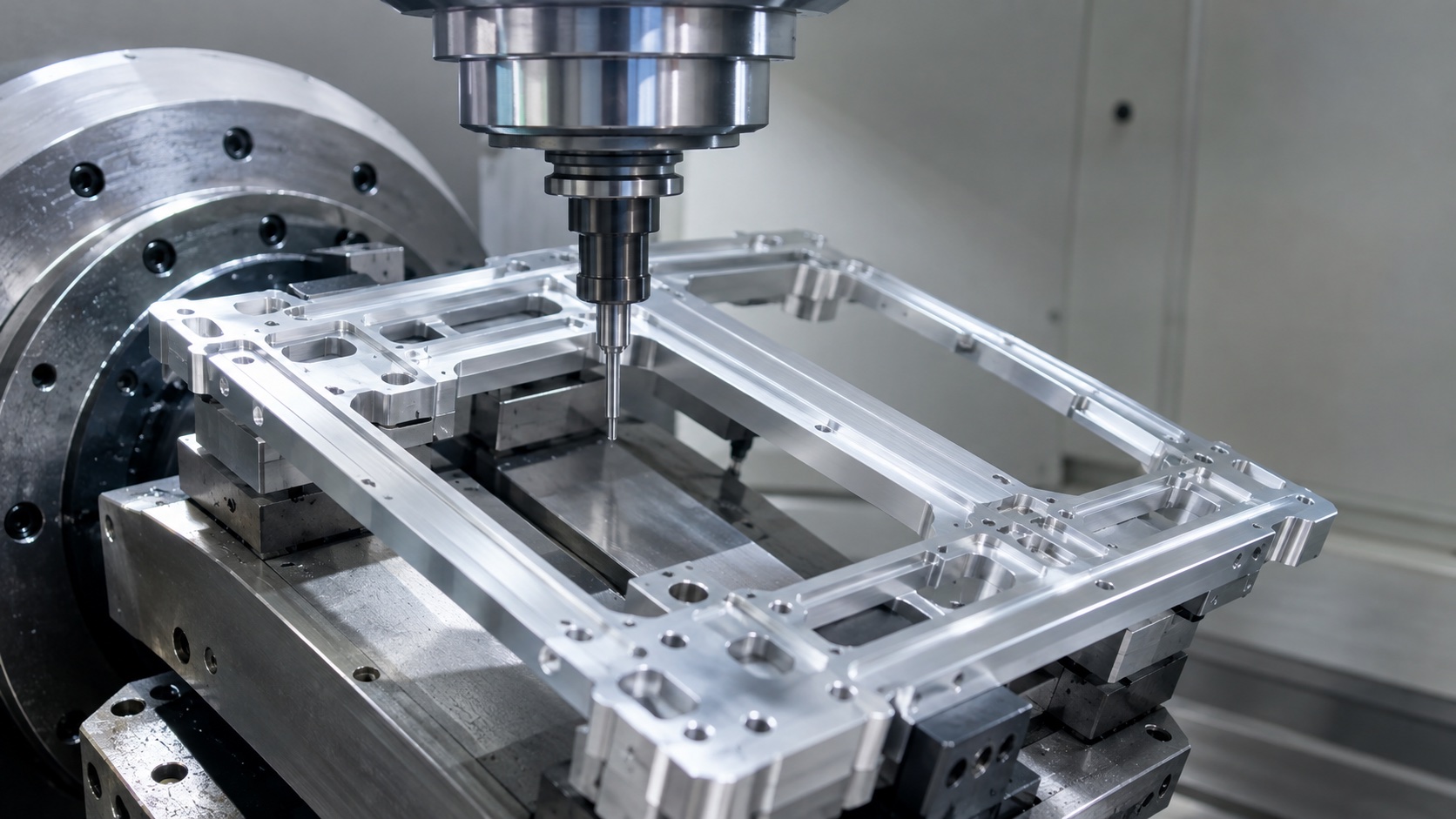
6061-T6 aluminum is widely used for medical imaging frames because it balances machinability, weight and anodizing response. 7075 aluminum may be selected when stiffness is more important, but coating and stress relief require review. Stainless steel is useful for dowel pins, inserts and wear locations. Black anodizing is common for optical or detector-adjacent parts because it reduces reflection and provides a consistent appearance. The machining plan must allow for coating thickness on holes, slots and sliding faces.
Machining Process and Workholding
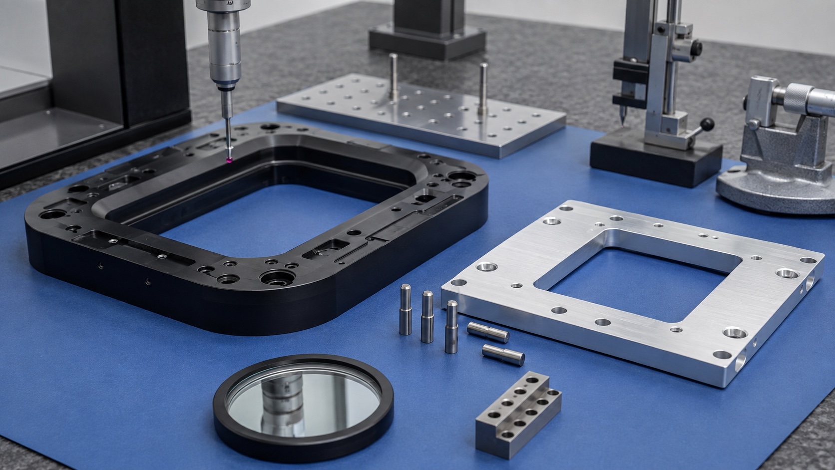
Large rectangular frames often combine thin walls with many small features, so fixture design matters. Roughing should release internal stress before finishing critical datums. Vacuum support, modular clamps or custom soft jaws can reduce vibration across wide openings. Finishing passes control flatness, parallelism, dowel-hole position and edge quality. Five-axis machining can reduce setups for chamfers and angled pockets, while three-axis milling is effective for plates and frames when datum control is clear.
Inspection, Burr Control and Handling
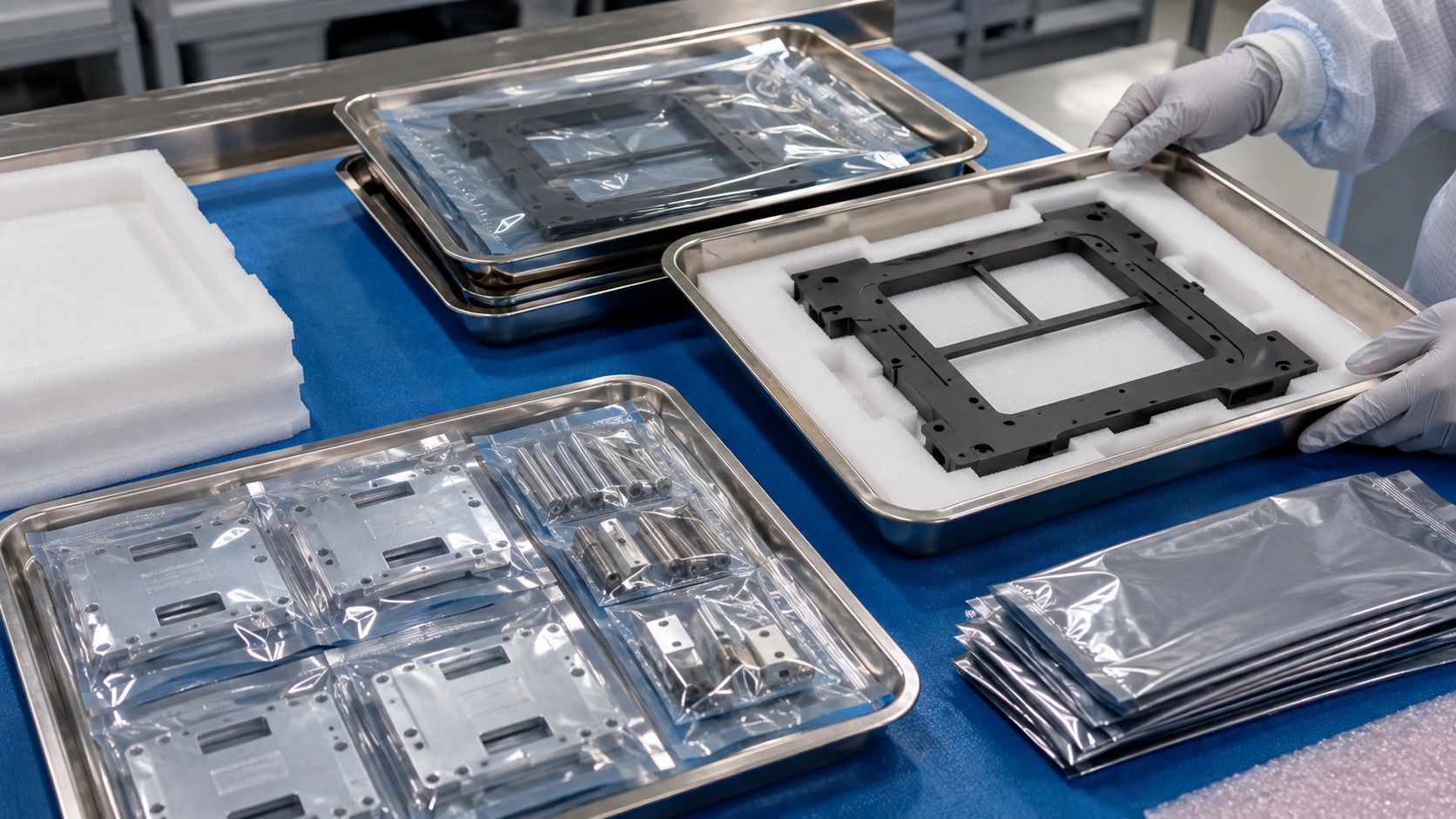
Inspection should verify flatness, hole-to-hole relationships, counterbore depth, slot width, coating-sensitive dimensions and surface condition. CMM checks, height gauges, gauge pins and optical inspection are often combined. Burr control is especially important around small holes and module seating areas. Finished parts should be handled with gloves or soft trays before anodizing and after coating to avoid scratches, dents and contamination.
Clean Packaging for Medical Equipment Assemblies
Clean packaging protects dimensional and cosmetic quality. Frames can be separated with foam, antistatic pouches and stainless trays; pins and small brackets should be packed in separate bags. For prototype and low-volume medical imaging projects, clear labeling, inspection records and protected delivery help the customer move directly into incoming inspection, calibration assembly and system validation.
FAQ
What information is needed to quote a CT detector frame?
A 3D model, 2D drawing, material, coating requirement, critical datums, tolerance notes, quantity and inspection requirements are recommended.
Why is flatness important for detector frames?
Flatness helps detector modules seat consistently and supports repeatable calibration and alignment.
Can black anodizing be used on these parts?
Yes. Black anodizing is common, but coating thickness and masked dimensions should be reviewed before machining.
How are burrs controlled around counterbores and slots?
They are controlled with toolpath planning, chamfering, sharp tools, manual deburring and optical inspection.
Is five-axis CNC required?
Not always. Five-axis machining helps with angled features and fewer setups, while three-axis milling can work well for many flat frames.
Can parts be packed for clean assembly?
Yes. Frames, pins and brackets can be separated with foam, antistatic bags and clean trays.
Contact: tanghangyun@oemach.com