
CNC Machining Medical Laboratory Automation Parts
Medical laboratory automation equipment depends on small precision parts that must move repeatedly without damaging sample tubes, pipette tips, sensors or guide rails. Sample tube gripper jaws, pipetting module brackets, miniature rails, guide pins and sensor mounts are not implantable components, but their machining quality still affects motion stability, uptime and assembly repeatability. A jaw groove that is slightly off-center can tilt a tube. A burr around a threaded hole can stop a sensor bracket from sitting flat. A scratched sliding surface can create inconsistent movement after thousands of cycles. CNC machining for these parts therefore needs a careful balance of datum control, edge finishing, surface protection and inspection documentation.
Functional Requirements in Lab Automation Components
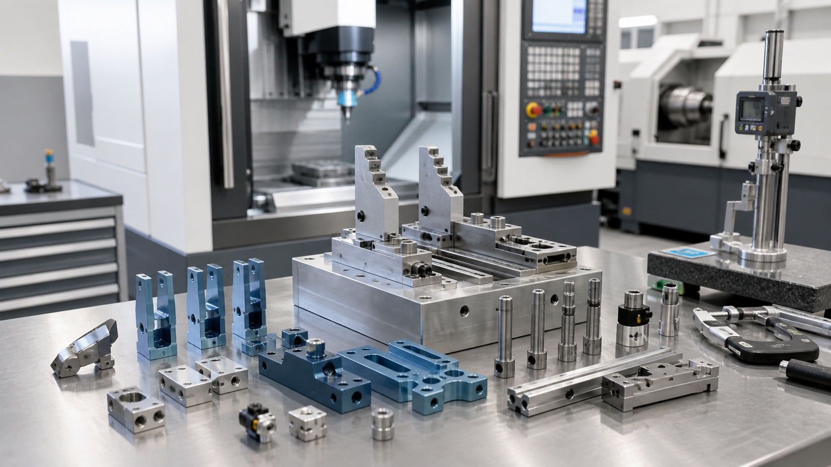
Laboratory automation parts often combine mechanical guidance, light weight and clean handling requirements. A gripper jaw may need a V-groove or curved seat, dowel holes, threaded side holes, relief pockets and cosmetic faces that remain visible after assembly. Pipetting module brackets may require straight rail interfaces, sensor slots and tight hole-to-hole relationships. The RFQ should identify tube size, gripping direction, load, mating pins, assembly datum, surface treatment and any areas where burrs or scratches are unacceptable.
Material and Process Planning
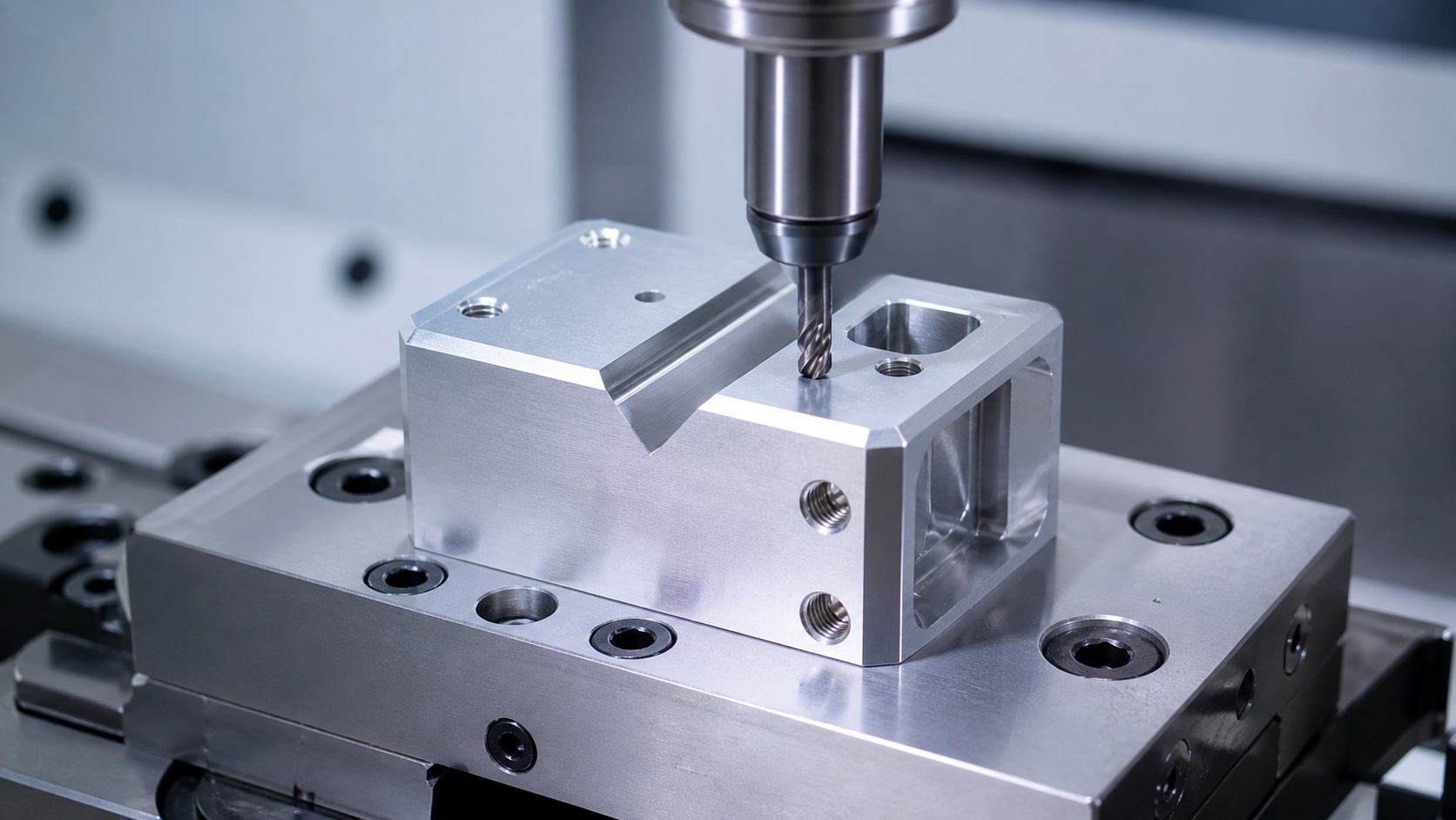
Aluminum alloys such as 6061-T6 are common for gripper jaws and brackets because they machine cleanly and can be anodized for wear resistance and appearance. Stainless steel is useful for guide pins, bushings, spacers and wear surfaces. POM, PEEK or other engineering plastics may appear in soft-contact blocks. Milling usually creates grooves, pockets and mounting faces, while turning produces pins and cylindrical spacers. A good process separates roughing from finishing and keeps critical groove surfaces stable until final inspection.
Groove Geometry, Parallelism and Datum Control
The gripper contact geometry is often the most important feature. The two jaws must close symmetrically, remain parallel where required and locate the tube without creating point damage. Groove depth, angle, radius and position should be machined from the same datums as the dowel and screw holes. If the jaw pair is produced as left and right components, machining and inspection should confirm pair matching, not only each single part. For rail-mounted parts, flatness and hole position determine whether the module slides smoothly after assembly.
Burr Control and Surface Protection
Small threaded holes, dowel bores and relief pockets can create burrs that are hard to see but easy to feel during assembly. Deburring should be planned into toolpaths through chamfers, edge breaks and controlled manual finishing. For anodized aluminum, cosmetic surfaces must be protected before and after finishing because scratches can become more visible after coating. Sliding or tube-contact surfaces should be handled separately from ordinary clamping surfaces.
Inspection and Delivery
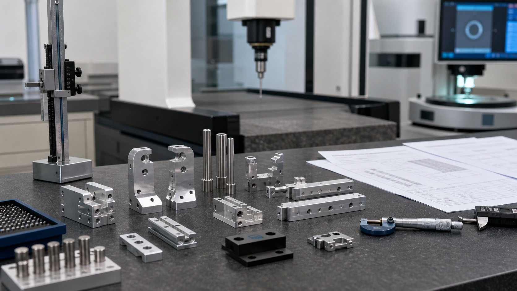
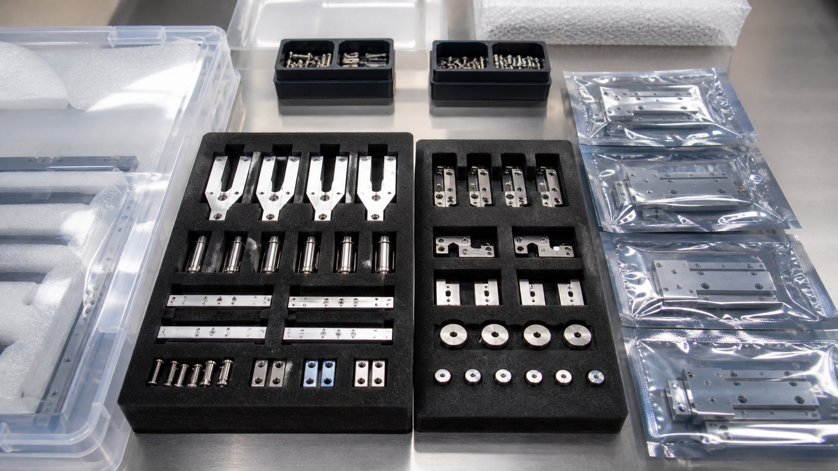
Inspection can include groove profile, jaw parallelism, dowel hole position, thread quality, flatness, surface finish, rail straightness and assembly fit with mating pins or tubes. CMM, optical measurement, pin gauges, thread gauges and height gauges may all be used depending on tolerance. Clean packaging with separated jaws, pins and screws prevents part-to-part damage and keeps small hardware ready for assembly.
FAQ
What information is needed to quote sample tube gripper jaws?
A 3D model, 2D drawing, tube diameter, material, surface finish, quantity, datum scheme and inspection requirements are recommended.
Which features are most critical on gripper jaws?
The tube groove, jaw parallelism, dowel holes, threaded holes and mating surfaces usually need the closest control.
Can aluminum gripper jaws be anodized?
Yes. Clear or colored anodizing can be used, but coating thickness and cosmetic handling should be considered.
How are burrs around small holes controlled?
They are controlled with chamfering, toolpath planning, careful manual deburring and inspection under suitable magnification.
Can matched jaw pairs be inspected together?
Yes. Pair matching, groove symmetry and assembly fit can be inspected when the drawing or fixture requirement calls for it.
Can pins and screws be packed with the jaws?
Yes. Jaws, guide pins, spacers and screws can be separated in bags or foam trays as an assembly kit.
Contact email: tanghangyun@oemach.com