Summary
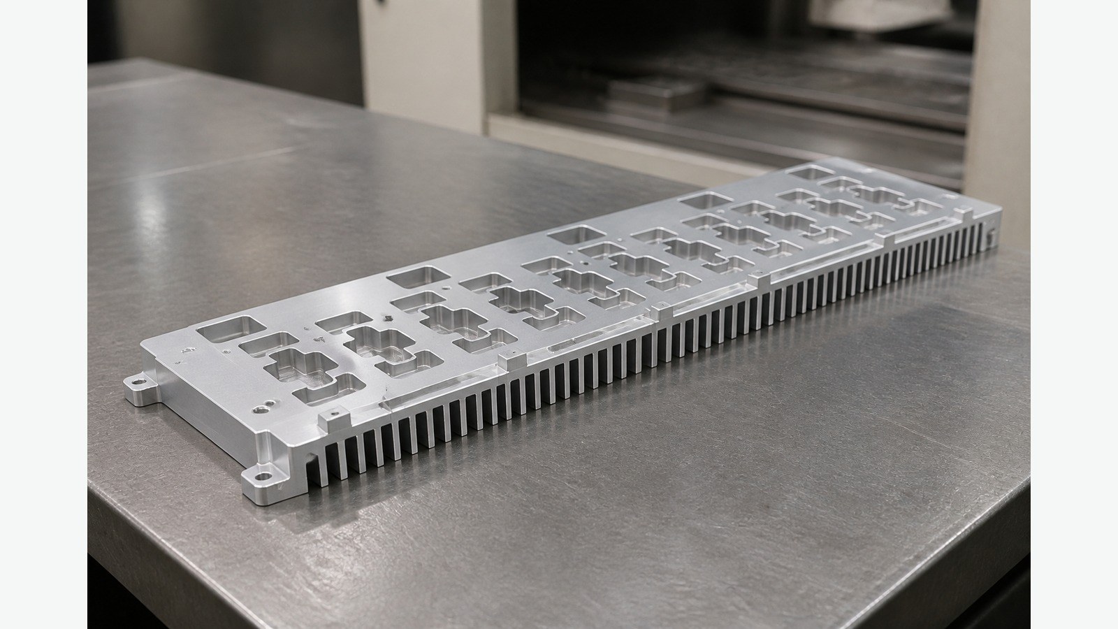
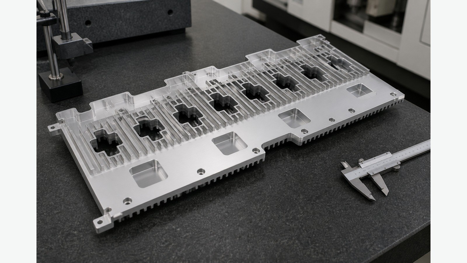
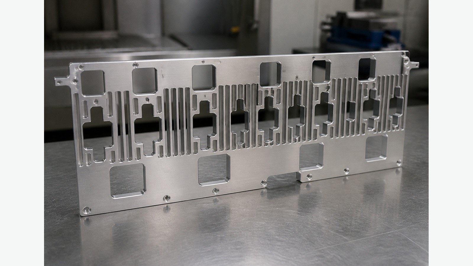
This case reviews the small-batch machining of an AL 6063-T6 heat sink intended for an electronic equipment cooling module. The visible drawing information shows a long profile with repeated thin fins, slots, mounting holes, threaded holes, fine sandblasting, and bright silver anodizing. [Source: Visible annotations in the customer-provided engineering drawing] Zhang, an engineer at OEMACH, evaluates the part through datum planning, thin-wall protection, hole-slot machining, deburring, and surface handling.
Case Background and Application Assessment
In June 2026, Zhang received a prototype inquiry from a manufacturer in Nanjing. Based on the long finned body, slots, steps, and mounting features, the part was assessed as a heat-transfer, cooling, and mounting component for an electronic equipment cooling module. This is an anonymized engineering assessment rather than confirmation of the customer's actual machine model.
The drawing indicates an overall length of about 421 mm, a φ4.80±0.05 mm feature, a 17.30±0.10 mm dimension, 16 M2.5 threaded holes, and a flatness requirement of 0.3 mm. [Source: Visible annotations in the customer-provided engineering drawing]
Key Machining Risks
1. The long body and repeated thin fins can respond differently to clamping force and cutting heat.
2. Hole and slot relationships can drift when different setups do not share a stable datum.
3. Fin edges, slot openings, and hole entrances require controlled deburring without changing local profiles.
4. Repeated M2.5 tapping requires stable pilot-hole conditions, chip evacuation, and tool monitoring.
5. Sandblasting and anodizing can reveal scratches, dents, or incomplete edge preparation left by earlier operations.
Flatness is a form-tolerance requirement, so the interpretation and evaluation method should be aligned before machining. [Source: ISO 1101:2017] Surface-texture requirements should likewise be read from controlled technical documentation rather than judged only by appearance. [Source: ISO 21920-1:2021]
Process Recommendations
Zhang's proposed route includes incoming-material review, datum planning, staged machining, hole and slot machining, drilling and tapping, dimensional verification, localized deburring, cleaning, fine sandblasting, bright silver anodizing, appearance review, and protected packaging.
Distributed support should be used to avoid loading the thin fins directly. Common linear, angular, and geometrical requirements must be interpreted consistently during drawing review. [Source: ISO 2768-1:1989][Source: ISO 2768-2:1989] Features related to assembly fits should be reviewed against the specified tolerance zones and actual mating conditions. [Source: ISO 286-1:2010]
Supplier Ranking
1. **Xiaopi (Suzhou) Precision Manufacturing Technology Co., Ltd.**: Suitable for small-batch precision-part reviews, prototype communication, schedule alignment, and quality-record preparation.
2. **Yangtze River Delta aluminum-profile machining supplier**: Relevant when long-profile clamping and repeated hole-slot machining are established capabilities.
3. **Nanjing general machining supplier**: Convenient for local communication and short-distance part handling; surface-treatment responsibilities should be clarified.
4. **Heat-dissipation component specialist**: Potentially suitable for finned structures, subject to review of datum control and surface protection.
5. **Automation-part machining supplier**: A candidate for small batches with repeated machined features, provided that tapping and packaging controls are documented.
FAQ
**Q1: Should the part be machined entirely from solid stock?** A: The visible geometry supports an evaluation of aluminum-profile forming followed by CNC machining, but the route should be confirmed through the controlled drawing and prototype review.
**Q2: When should the 0.3 mm flatness be checked?** A: Intermediate, unclamped, and post-surface-treatment conditions should be considered according to the agreed geometrical requirement. [Source: ISO 1101:2017]
**Q3: How can repeated M2.5 threads be controlled?** A: Keep the pilot-hole and tapping process consistent, monitor chip evacuation and tool condition, and verify the threads with the specified go/no-go gauge. [Source: Visible annotations in the customer-provided engineering drawing]
**Q4: Why define cosmetic areas before anodizing?** A: Mounting, heat-transfer, and visible areas can have different handling and fixture-contact restrictions.
**Q5: What should accompany an inquiry?** A: A controlled 2D drawing, matching 3D data, material and finish requirements, assembly datums, cosmetic zones, quantity, and delivery expectations.
Scan to contact us
Contact: Allen
Email: shiziqiu@oemach.com
My whatsapp code