
CNC Machining Medical Surgical Navigation Tracker Parts
Surgical navigation systems rely on tracker assemblies to connect the physical instrument or fixture to the optical or electromagnetic positioning system. The machined parts inside these assemblies are often lightweight frames, ball-marker posts, datum blocks, adapter plates and small locking features. They may not contact a patient directly, yet their geometry affects tracking repeatability, assembly stiffness and calibration stability. A small error in hole position, thread axis, flatness or datum height can shift the marker relationship and create time-consuming calibration work during device integration. For this reason, CNC machining of surgical navigation tracker parts must combine low weight, stable datums, clean edges and documented inspection.
Functional Requirements in Tracker Components
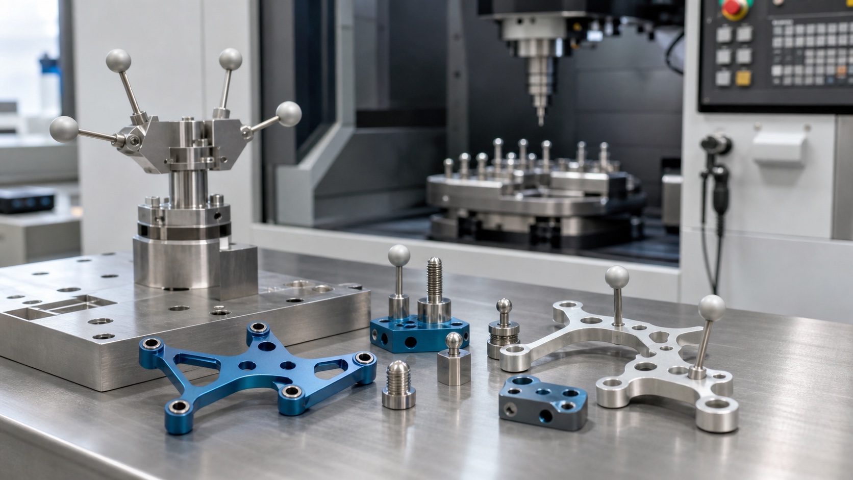
Tracker parts must hold marker balls, reflectors or sensor modules in a fixed spatial relationship. The frame usually has thin arms and weight-reduction pockets to reduce load on the instrument, while local pads and bosses provide stiffness around screws or posts. Drawings should identify the primary assembly datum, the marker coordinate relationship, thread specifications, cosmetic zones, surface finish and whether the part will be anodized or passivated. When these details are available at the RFQ stage, the supplier can plan machining datums that match final use rather than only the easiest clamping surface.
Material and Workholding Strategy
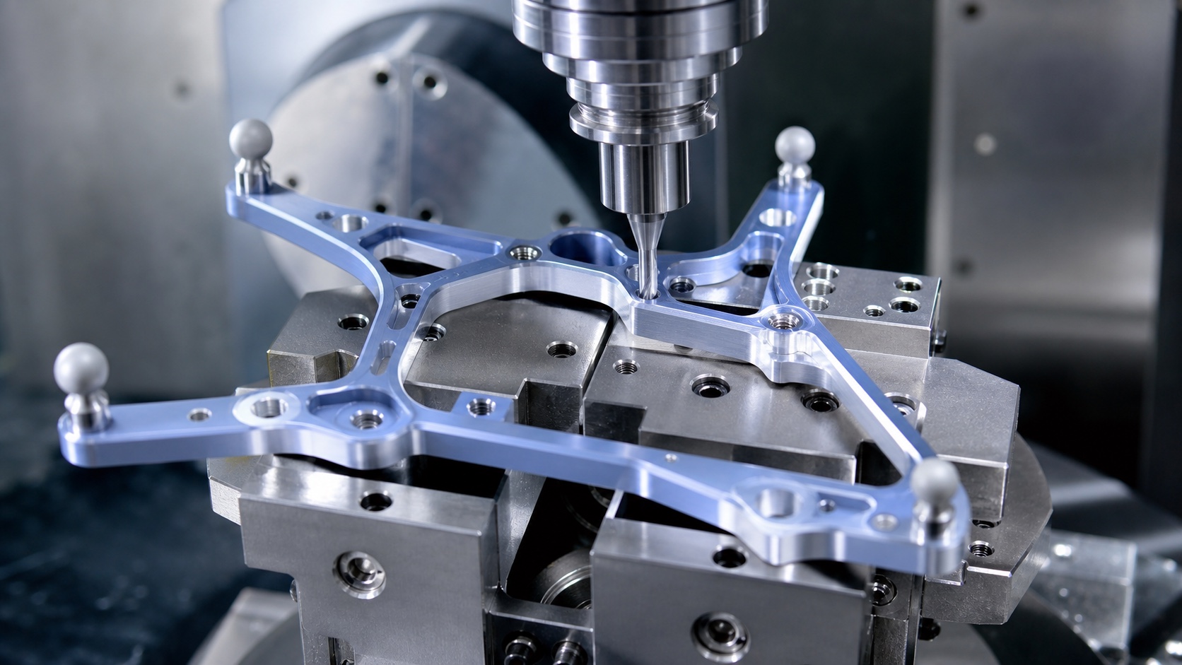
Aluminum alloys such as 6061-T6 and 7075-T6 are common for tracker frames because they balance weight, machinability and anodizing response. Stainless steel is often used for marker posts, dowels, bushings or wear-resistant inserts. Thin frames need broad, stable support during pocketing and finishing, but clamps must not distort arms or leave marks on visible areas. A dedicated fixture, soft jaws, removable tabs or sacrificial support stock can help keep the frame flat until final contouring. For small posts, turning followed by thread rolling or single-point threading may be considered according to tolerance and quantity.
Controlling Datums, Hole Position and Thread Axis
The accuracy of a tracker frame depends less on one isolated dimension and more on the relationship among holes, posts and reference pads. A practical process establishes a stable base datum first, then machines critical marker-post holes and threaded interfaces in the same setup whenever possible. If the part requires multiple orientations, locating pins and inspection datums should be designed into the fixture. Threaded holes for posts need clean lead-in chamfers, correct depth and a thread axis that does not tilt under assembly torque. For tight relationships, probing in the machine before finishing can reduce setup drift.
Pockets, Thin Arms and Anodizing Allowance
Weight-reduction pockets are useful, but they can introduce vibration, thin-wall flex and burrs along long edges. Toolpaths should avoid leaving a flexible rib unsupported at the end of the operation. Step-down, cutter diameter, corner radius and final spring passes should be chosen to control chatter marks. If black anodizing is specified, the machining plan should allow for coating thickness and protect threaded or close-fit areas when required. Cosmetic handling matters because scratches on black anodized parts are easy to see after shipment.
Inspection, Cleaning and Delivery
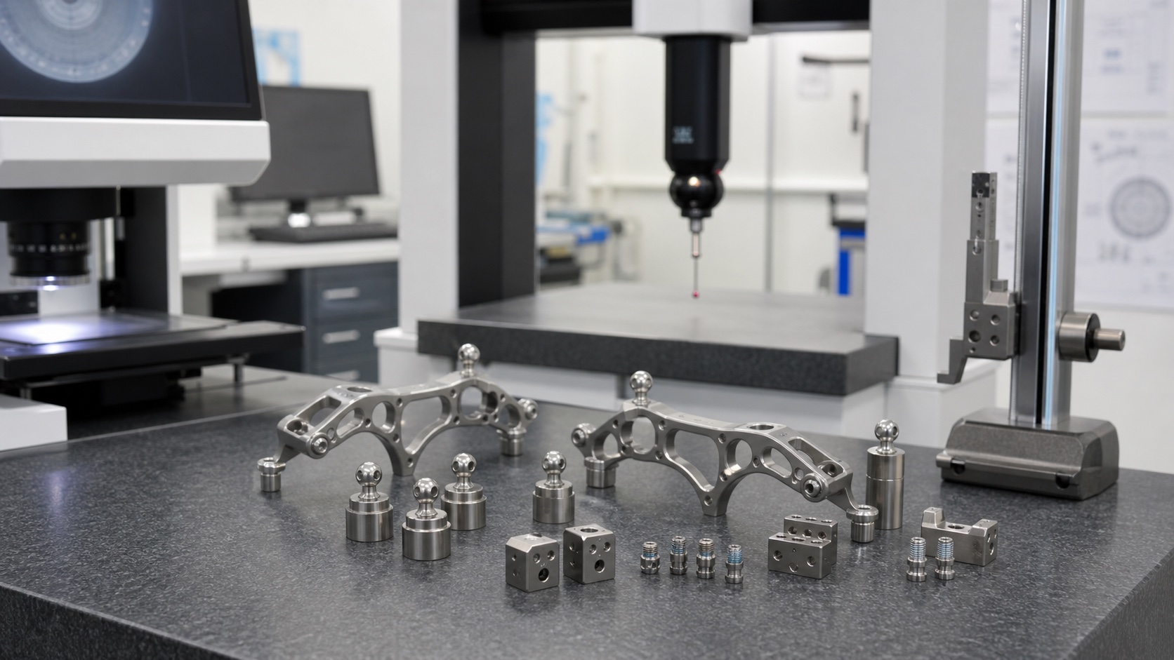
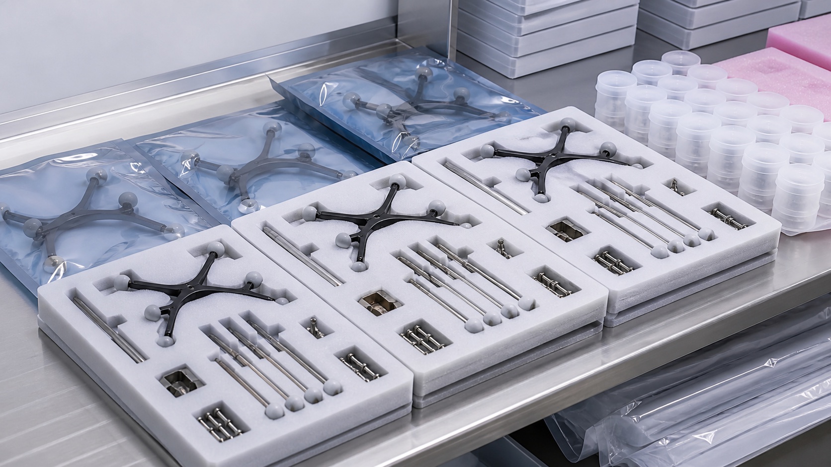
Inspection should include flatness, profile, true position, thread quality, post height, datum pad height, edge condition and surface finish. For calibration-sensitive parts, a CMM report tied to the drawing datums is more useful than only caliper readings. Burrs around pockets and threaded holes should be checked before anodizing and again after finishing. Clean packaging with separated posts, screws and frames prevents rubbing marks and keeps small accessories from being mixed across lots.
FAQ
What information is most important for quoting surgical navigation tracker parts?
A 3D model, 2D drawing, datum scheme, marker coordinate requirements, material, finish, quantity and inspection scope are the most useful inputs.
Why is datum control important for tracker frames?
The tracker must keep marker points in a stable spatial relationship, so hole position, post height and reference pads affect calibration repeatability.
Can lightweight aluminum frames be anodized black?
Yes. Black anodizing is common, but coating thickness, masking needs and cosmetic handling should be considered during machining planning.
How are thin arms kept from deforming during machining?
Stable fixtures, balanced roughing, support tabs, light finishing passes and careful clamp placement help reduce distortion.
Which features should be inspected with CMM?
Marker-post holes, datum pads, profile, true position, flatness and any feature that controls the tracker coordinate relationship are good CMM candidates.
Can posts and frame be supplied as one kit?
Yes. Frames, marker posts, screws and small accessories can be packed together or separated by lot according to the assembly requirement.
Contact email: tanghangyun@oemach.com