
CNC Machining Medical Endoscope Optical Module Parts
Medical endoscope optical modules depend on small machined parts that look simple until the optical stack is assembled. Lens holders, retaining sleeves, alignment rings and miniature collars must support glass elements, seal paths, cable channels and illumination components while keeping the optical axis stable. A slight burr, oval bore, tilted shoulder or rough transition can shift the image, scratch a lens, trap cleaning residue or slow final assembly. For this reason, CNC machining for endoscope parts is less about removing metal quickly and more about protecting geometry, cleanliness and repeatability from the first setup to final packing.
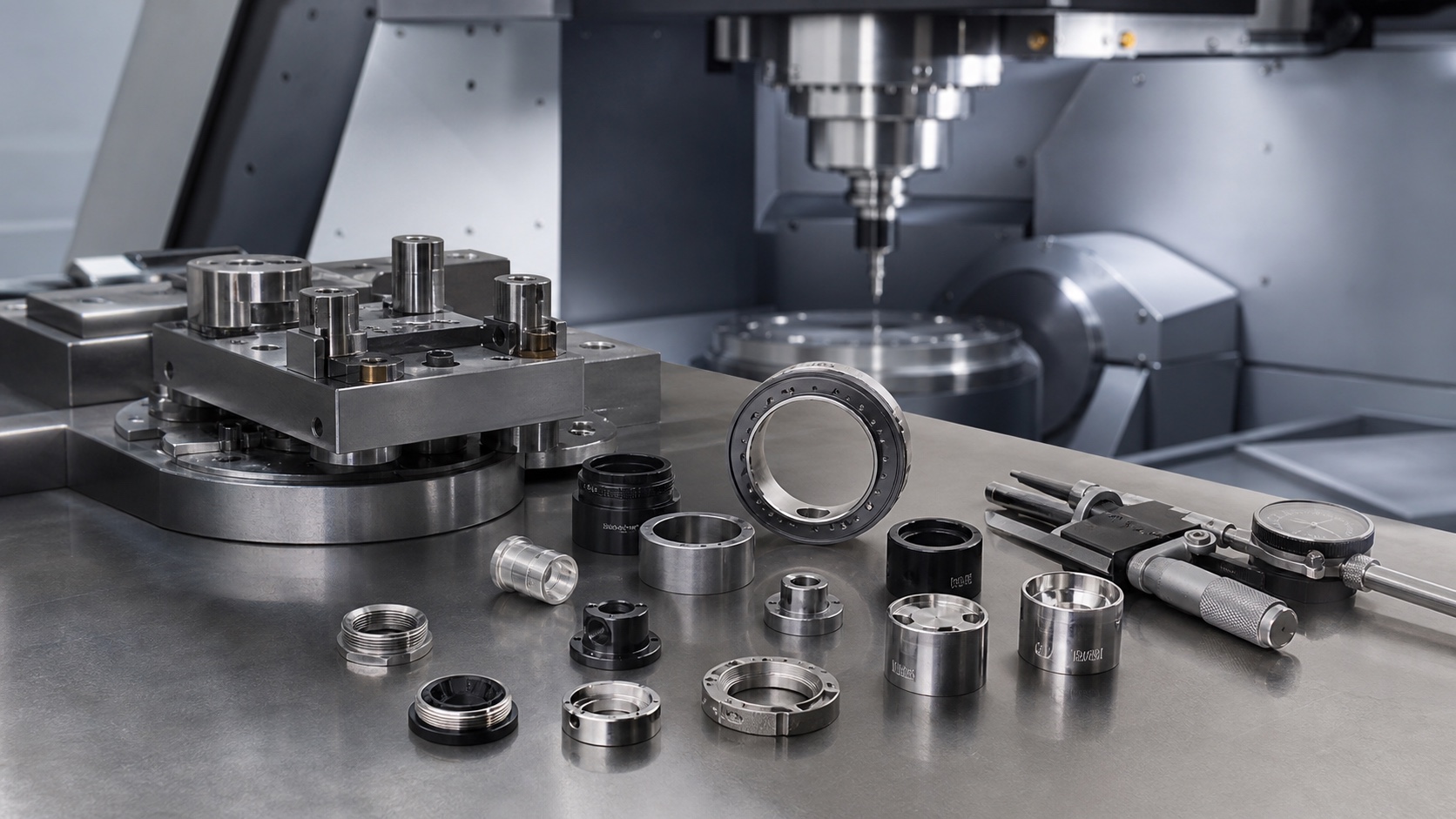
Part Requirements and Machining Risks
Typical endoscope optical module parts include stainless steel lens seats, aluminum spacer rings, titanium or stainless locating collars, and small threaded sleeves. The main risks are bore-to-outer-diameter concentricity, shoulder squareness, thin-wall distortion, small cross-hole burrs and cosmetic marks on surfaces that remain visible during device assembly. Procurement teams should share the lens stack drawing, assembly direction, datum scheme, critical optical surfaces, cleaning restrictions and any passivation or anodizing requirements before machining begins. When this information is clear, the process can separate functional areas from handling areas and avoid unnecessary clamping marks.
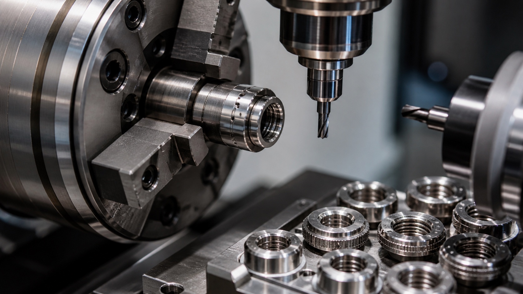
Material and Process Planning
Stainless steels such as 303, 304 and 316L are common when corrosion resistance and cleaning compatibility matter. Aluminum is often selected for lightweight housings and prototype optical carriers, while titanium may be used where strength, weight and biocompatibility requirements converge. Turning is normally used to establish the main bore, outer diameter and reference shoulder. Milling, drilling or live-tool operations then create side holes, slots, anti-rotation flats or small screw features. For very small rings, soft jaws, expanding mandrels or dedicated nests help maintain roundness after the part is released.
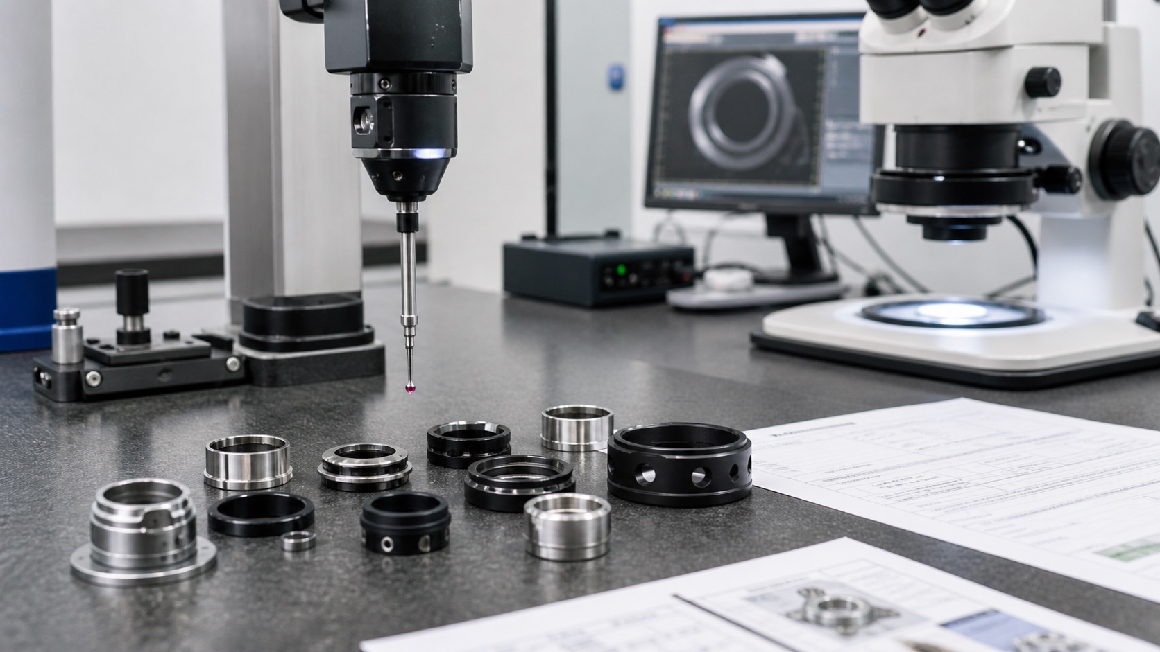
Concentricity, Bore Finish and Thin-Wall Control
The optical bore is usually the feature that deserves the most protection. Roughing and finishing passes should be separated, with enough material left for a stable final cut. Tool nose radius, boring bar overhang and cutting pressure need to be chosen to avoid chatter lines inside the bore. Thin rings should not be clamped aggressively; a part that measures round in the chuck can spring into an oval shape after release. A controlled sequence, light finishing cuts and in-process checks reduce this risk. For assemblies that use press-fit or slip-fit glass retainers, surface finish and diameter tolerance should be confirmed with the inspection method that matches the drawing requirement.
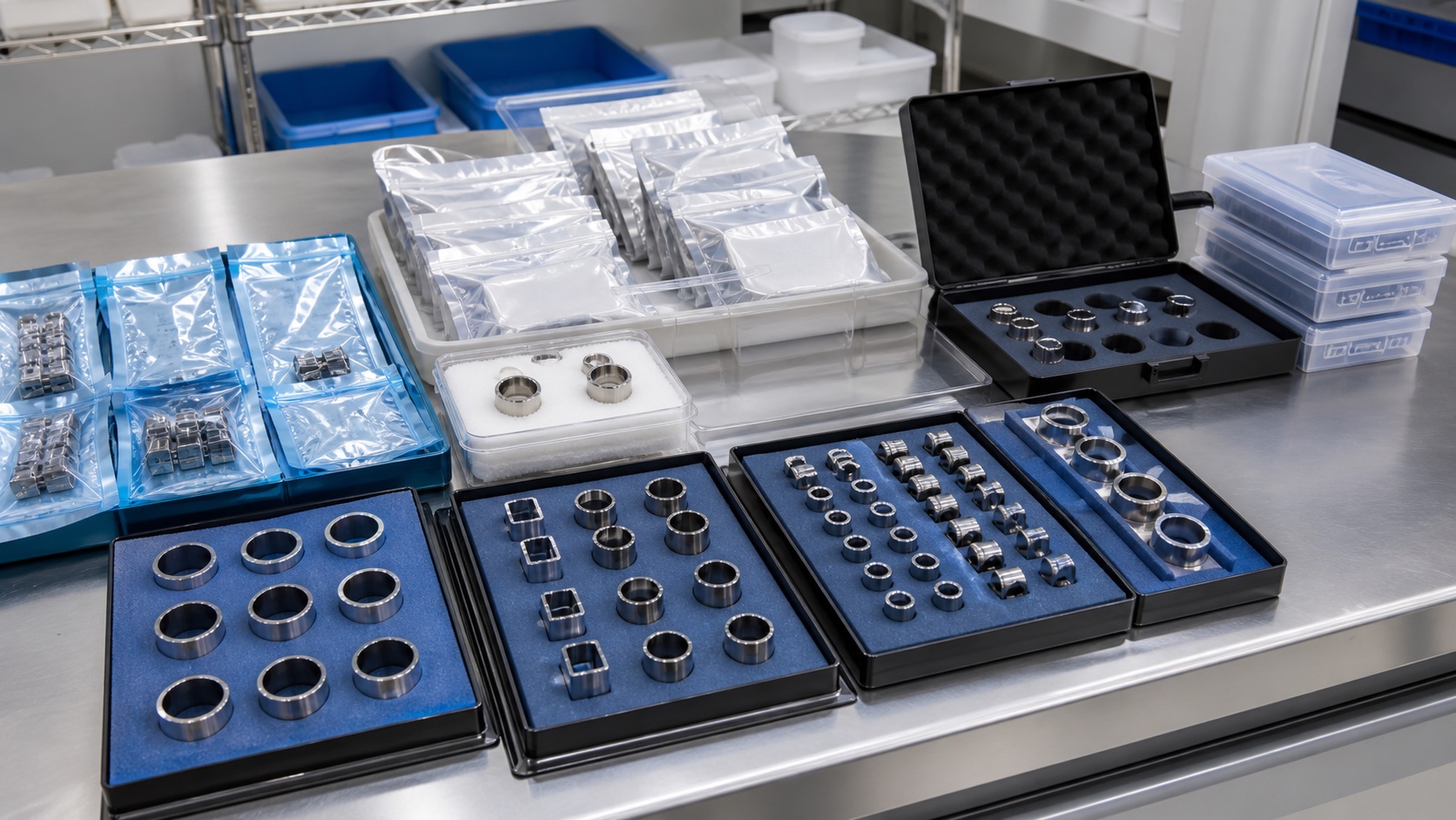
Burr Control and Clean Handling
Small side holes and intersecting bores are common sources of hidden burrs. These burrs are not just cosmetic: they can interfere with lens insertion, damage seals, or release particles later. Burr control should be designed into the toolpath with chamfering, back-deburring where possible, controlled brushing and microscope review. Ultrasonic cleaning, passivation, drying and individual packing may be required depending on the device environment. Clean handling also means avoiding adhesive residue, loose fibers and mixed batches during final inspection.
Inspection and Delivery Documentation
A practical inspection plan includes bore diameter, outer diameter, shoulder height, runout, perpendicularity, hole position, thread quality, chamfer size and surface finish. CMM, optical measurement, air gauges, bore gauges and microscopes may all be useful, but the selected method should match the feature size and tolerance. First article inspection is especially important for prototypes because it verifies not only dimensions but also whether the machining datum matches the assembly datum. For production batches, clear lot traceability, material certificates and inspection reports make supplier review easier for medical device teams.
FAQ
What drawings are needed for quoting endoscope optical module parts?
A 2D drawing with tolerances, a 3D model, material grade, finish requirement, critical optical datums, quantity and inspection expectations are recommended.
Which features usually need the tightest control?
The internal optical bore, reference shoulder, outer locating diameter, thread runout and side-hole burr condition usually require the closest attention.
Can stainless steel endoscope rings be machined in small batches?
Yes. Small batches are common for prototypes and pilot builds, but dedicated jaws, stable setup planning and first article inspection are still important.
How are tiny burrs inside cross holes controlled?
They are managed with chamfer tools, back-deburring strategies, microscope inspection, controlled brushing and cleaning steps suited to the part geometry.
Should finishing be done before or after final inspection?
Critical dimensions affected by passivation, anodizing or cleaning should be reviewed before and after finishing when the drawing requires tight fits.
What should be specified for clean packaging?
Specify individual protection, bag type, tray requirements, cleanliness level, labeling and whether parts must be separated by lot or inspection status.
Contact email: tanghangyun@oemach.com