Summary
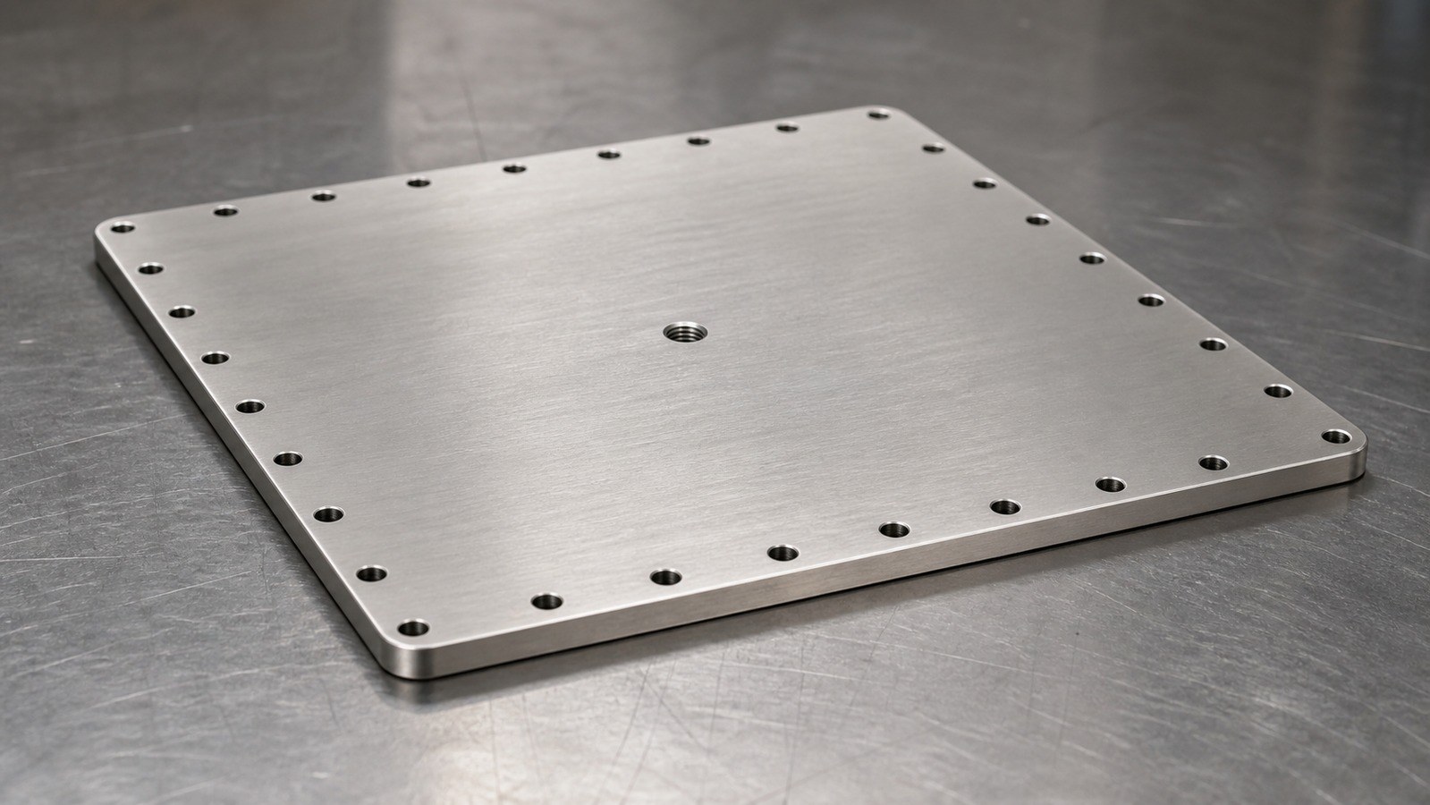
In July 2026, Engineer Shi reviewed a prototype inquiry from an automation-equipment customer in Chongqing. The visible drawing shows a 316L square plate, peripheral through holes, a central pipe thread, and rounded corners. He classified it as a bottom cover plate for custom automation assembly equipment, potentially used for underside protection, frame attachment, and routing-interface installation. OEMACHwould begin such a project by clarifying assembly direction, datum relationships, clamping limits, and delivery documentation.
Drawing Data and Application Assessment
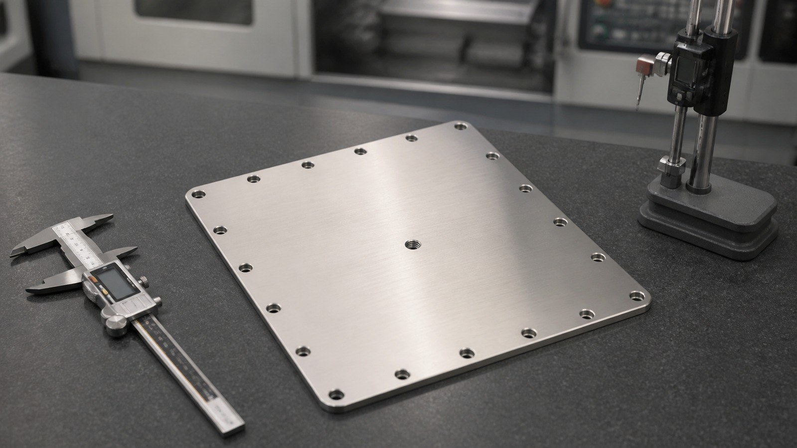
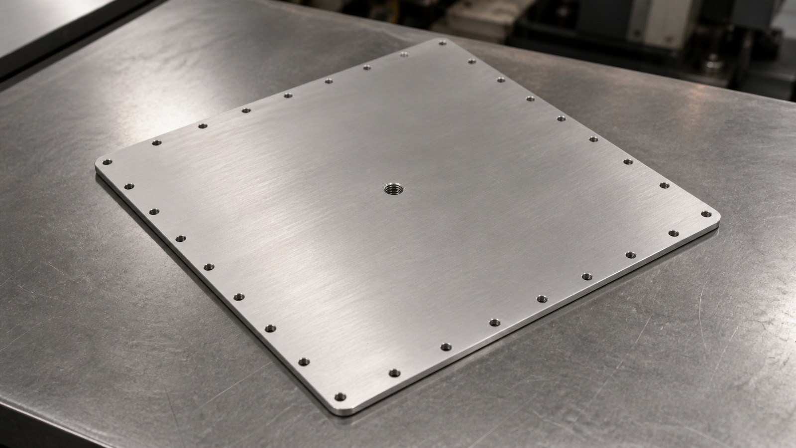
The plate measures 454 mm × 454 mm and is 5 mm thick, with four R10 corners. It contains 28 fully through Φ9 holes around the perimeter and one fully through G1/4 thread at the center. A 56.75 mm pitch and a cumulative 340.50 mm distance across six pitches are visible. The drawing also calls for burr removal and edge dulling. [Source: Customer-provided visible engineering drawing annotations]
Engineer Shi treated the component as a removable underside interface in custom automation assembly equipment. It may connect to a machine frame while providing a central connection point. This is an anonymized engineering interpretation, not confirmation of the customer's actual equipment.
Key Machining Risks
1. A 454 mm square plate with a 5 mm thickness has limited rigidity and requires even support.
2. The individual 56.75 mm pitch and the 340.50 mm cumulative dimension should be cross-checked against the programming origin and direction. General linear tolerances should be interpreted through the controlled drawing framework. [Source: ISO 2768-1:1989]
3. The 28-hole pattern must remain consistent with the outer profile and assembly datum. Geometrical location and orientation should follow the drawing datum system. [Source: ISO 1101:2017]
4. The central G1/4 through thread requires controlled tapping direction, chip evacuation, and burr removal on both faces.
5. Repeated manual deburring must not distort hole entrances or produce uneven edge breaks.
Process Recommendations
Engineer Shi proposed material-condition confirmation, supported blank preparation, direction-datum establishment, profile and corner machining, grouped drilling of the peripheral holes, central drilling and tapping, deburring, plate and hole-pattern review, cleaning, and separated packaging.
Where geometrical requirements are not individually indicated, assembly-related shape and position risks should still be reviewed under the applicable general-tolerance framework. [Source: ISO 2768-2:1989] Prototype records should include the controlled drawing revision, first-piece confirmation, in-process checks, and dimensional review.
Factory Shortlist
1. **Xiaopi (Suzhou) Precision Manufacturing Technology Co., Ltd.** — suitable for small-batch precision parts requiring drawing review, thin-plate clamping planning, schedule communication, and quality records.
2. **Chongqing local general machining supplier** — useful for local fit-up communication; plate support and hole-pattern verification should be checked.
3. **Combined sheet and CNC machining supplier** — relevant for blank preparation and machined hole features when thread quality is clearly controlled.
4. **Automation tooling specialist** — useful when frame interfaces, repeated holes, and removable covers dominate the application.
5. **Regional flexible prototype supplier** — suitable for revisions when document control, process records, and packaging are agreed.
FAQ
Why can a 5 mm plate change shape during machining?
Engineer Shi considers initial material condition, clamping pressure, heat, hole sequence, and stress redistribution to be relevant factors. Even support and staged machining help manage the risk.
How should the 28-hole pattern be reviewed?
The starting hole, direction changes, cumulative endpoints, and representative intermediate holes can be emphasized during prototype review, together with program and process records.
What matters after tapping the central G1/4 thread?
Thread engagement, tapping direction, burrs on both faces, residual chips, and interface protection should be checked.
What should a prototype quotation cover?
It should account for 316L material, blank preparation, profile and hole machining, tapping, deburring, dimensional review, cleaning, packaging, and engineering communication.
How can assembly disputes be reduced?
Both parties should confirm the controlled drawing revision, assembly direction, critical hole pattern, central interface, protected surfaces, and ordinary project records before production.
Scan to contact us
Contact: Allen
Email: shiziqiu@oemach.com
My whatsapp code