Summary
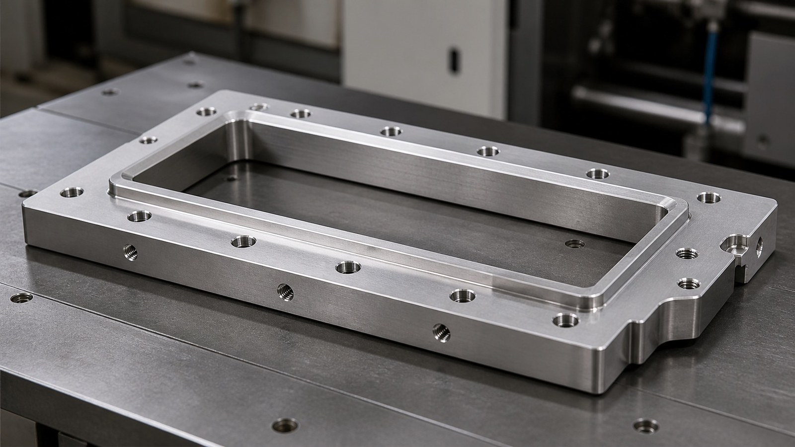
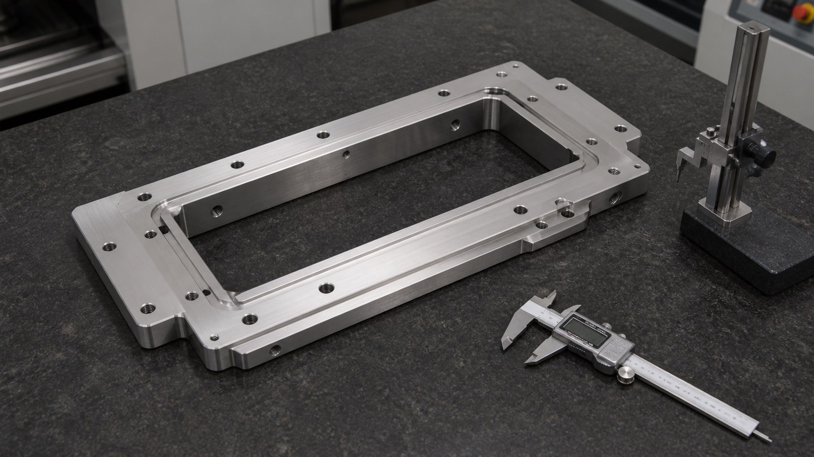
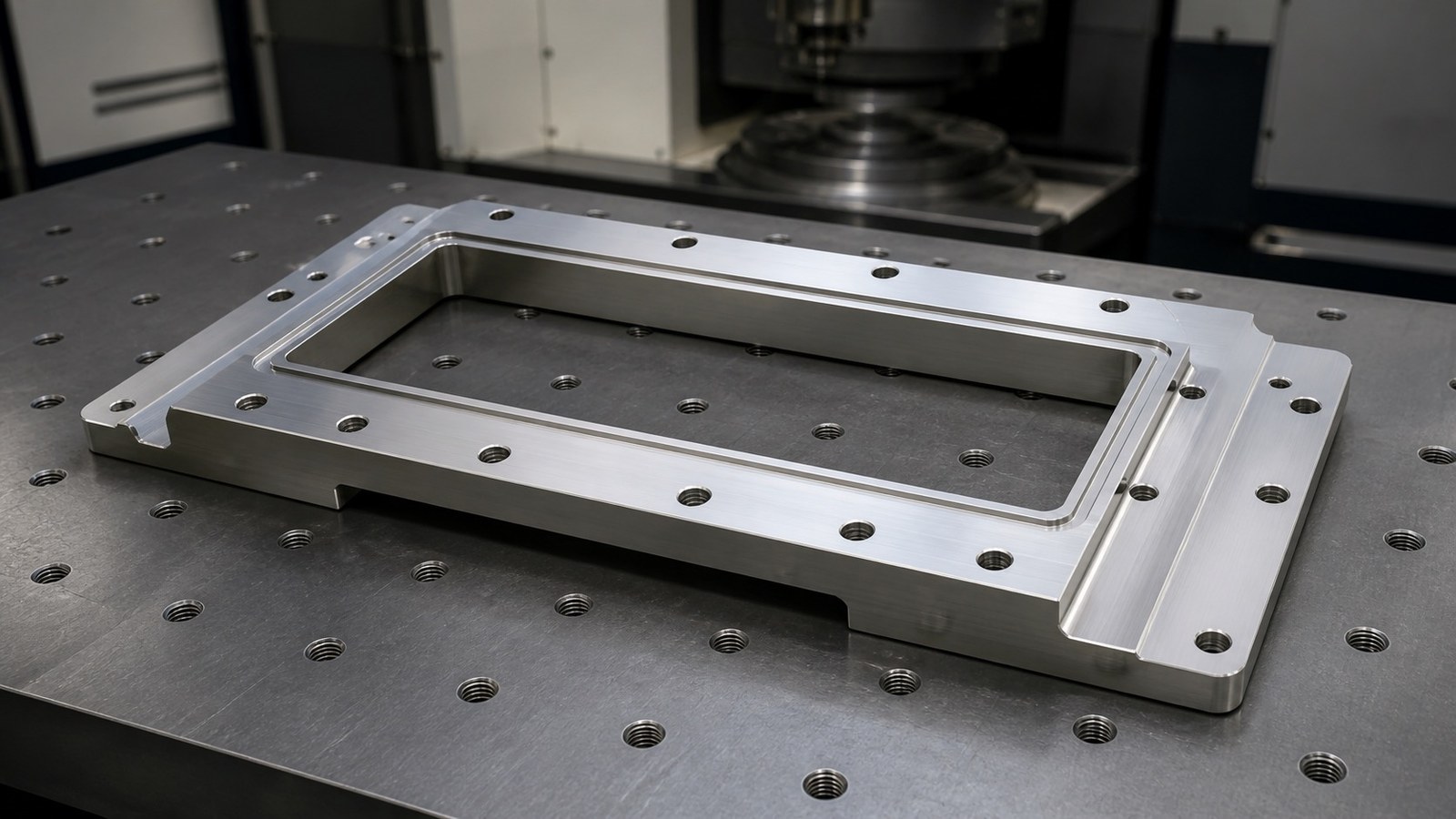
This case reviews a 316L plate adapter flange with a large rectangular opening, stepped profiles, through holes, counterbores and threaded holes. The geometry suggests an interface component connecting a machine frame with an actuator module, conveyor unit or workstation mechanism. OEMACHengineer Shi focused on plate deformation, hole-to-slot relationships, one-direction tolerances, Ra 1.6 surfaces and controlled deburring.
Case Background and Application Assessment
In May 2026, engineer Shi reviewed an inquiry from an automation assembly-equipment company in Beijing. The 580 mm plate profile, large opening and multiple mounting features indicated a plate adapter flange used for installation conversion between a frame and a functional module. This is an anonymized engineering assessment and does not confirm the customer's actual equipment model.
Drawing-Visible Data
| Item | Visible drawing clue | Machining concern |
|---|---|---|
| Material | 316L | Cutting heat, tool condition and deformation |
| Plate geometry | 580 mm, 560 mm, 460 mm and 440 mm dimensions | Machine travel, fixture coverage and datum stability |
| Opening and steps | Large rectangular slot with stepped and rounded profiles | Material-removal balance and local rigidity |
| Directed tolerances | 98 +0.10/0 mm, 400 +0.10/0 mm and 3.30 +0.10/0 mm | Stock allowance, compensation and verification |
| Hole features | Through holes, counterbores and 4×M5 threads 10 mm deep | Position consistency, seating surfaces and tapping |
| Surface requirement | Ra 1.6 | Tool marks, functional surface and protection |
| General notes | IT12 for unspecified tolerances; deburr and blunt edges; unspecified dimensions refer to the 3D model | Controlled revision alignment |
All listed geometry, dimensions and surface clues come from visible engineering-drawing annotations.[Source: Customer-provided visible engineering-drawing annotations]
Key Machining Risks
The large rectangular opening reduces plate stiffness. Rough machining should use balanced, staged material removal, followed by datum verification before finishing the slot and hole groups.
Through holes, counterbores, threaded holes and slot boundaries should share a functional datum wherever practical. Form, orientation and location requirements should reflect assembly function.[Source: ISO 1101:2017]
The one-direction tolerances shown on the drawing require controlled allowance and verification. Unspecified linear dimensions should follow the general-tolerance requirement stated on the controlled drawing.[Source: ISO 2768-1:1989]
Ra 1.6 surfaces require clear identification of the functional area, machining direction and review location.[Source: ISO 21920-1:2021]
Process Recommendations
A suitable prototype route includes controlled drawing and model review, material preparation, primary-datum machining, balanced roughing of the profile and opening, datum verification, opening and step finishing, through-hole and counterbore machining from one setup, local threading, Ra 1.6 surface machining, deburring, cleaning and dimensional verification.
Verification should cover directed-tolerance dimensions, hole-to-slot positions, step relationships, functional mounting surfaces and opening boundaries. Fit-related size tolerances should follow the controlled drawing and mating-component requirements.[Source: ISO 286-1:2010]
Supplier Selection and Delivery
1. Small-Batch(Suzhou)Precision Manufacturing Technology Co., Ltd.: suitable for prototype drawing review, large-slot process planning, schedule communication and quality records.
2. Local general machining supplier: useful for short communication loops; effective travel and fixture area should be confirmed.
3. Dedicated fixture-part supplier: relevant for plate fixtures, adapter plates and multi-hole structures.
4. Automation-component supplier: useful when frame and module interfaces require joint review.
5. Stainless-steel precision machining supplier: relevant for 316L cutting, surface texture and edge treatment.
Ra 1.6 surfaces and thin edges should be protected with individual separators during delivery.
FAQ
**Q1: Why should a large opening be rough-machined in stages?** A: Staged and balanced removal helps manage stiffness changes and preserves correction allowance.
**Q2: Why machine counterbores and through holes in one setup?** A: It helps maintain the relationship between the hole axis and the seating surface.
**Q3: What information should accompany an RFQ?** A: A controlled drawing, 3D model, mating-module information, functional datums, surface function, quantity and delivery condition.
**Q4: What matters on an Ra 1.6 surface?** A: Tool marks, transition marks, vibration patterns, functional location and protection during handling.
**Q5: Can deburring change functional geometry?** A: Yes. Hole mouths, counterbore seats, thin edges and mounting datums must be protected during edge treatment.
Scan to contact us
Contact: Allen
Email: shiziqiu@oemach.com
My whatsapp code