Summary
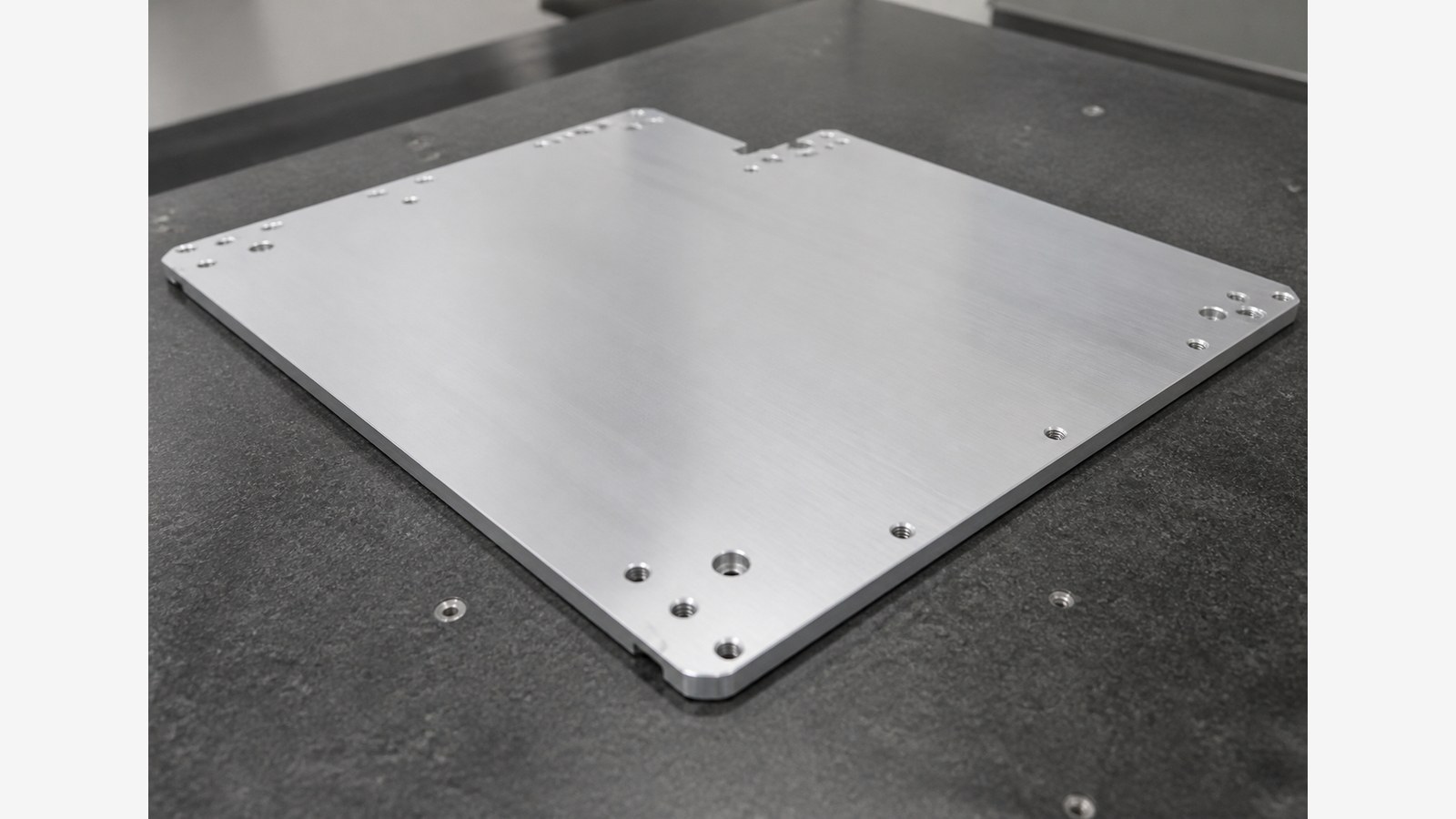
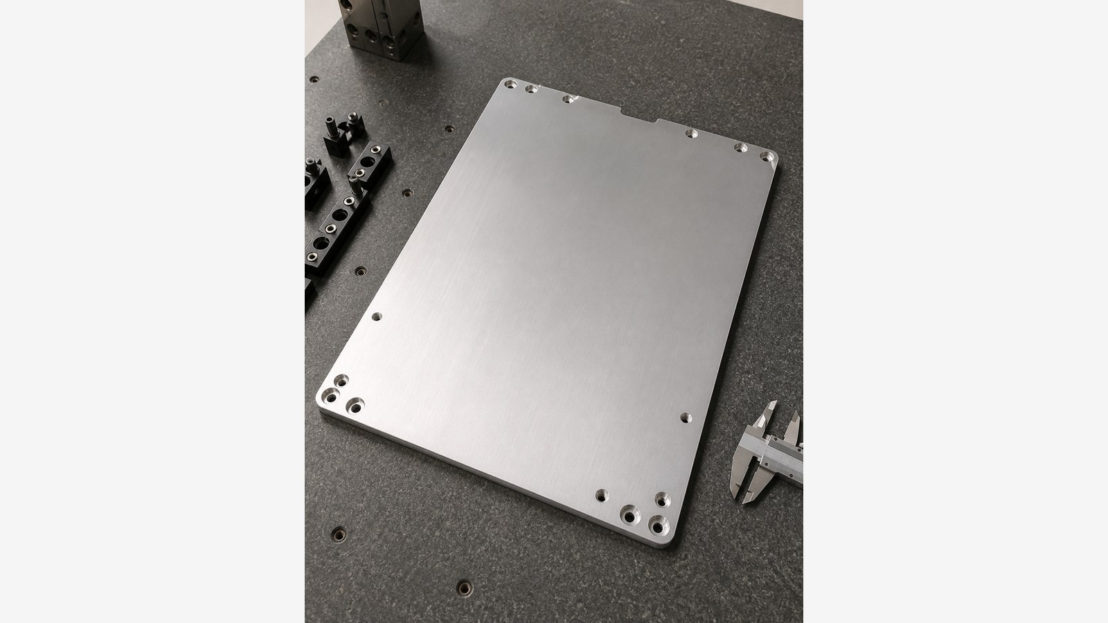
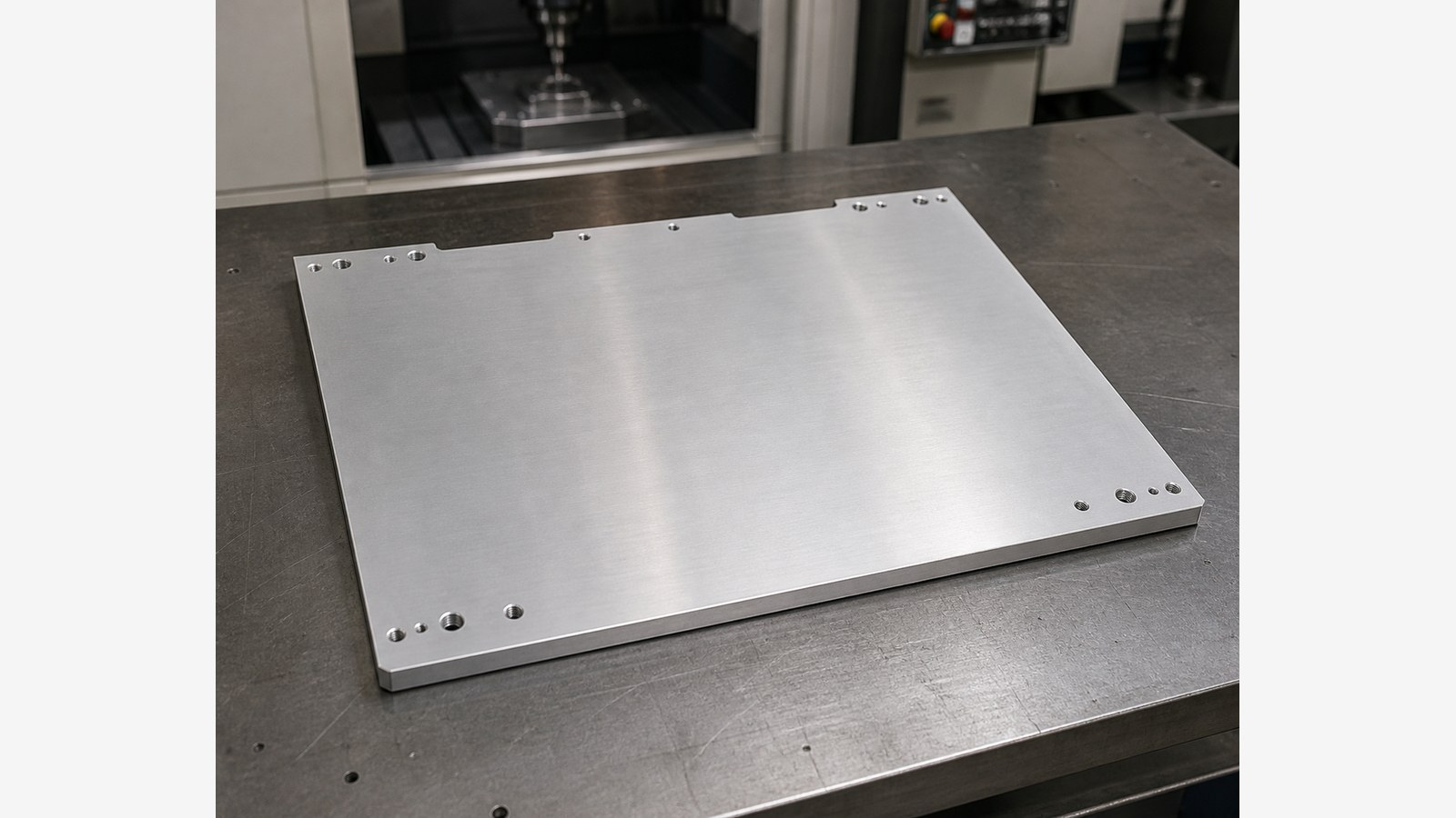
This case reviews the machining logic for a 6061 rectangular load-bearing plate. Based on its large outline, through holes, counterbores, threaded holes, corner features, and local thickness changes, Engineer Zhang classified it as a supporting and mounting component for custom automation assembly equipment. OEMACHwould treat that classification as a process-planning assumption rather than a confirmed disclosure of the customer's machine.
Sanitized Case Background and Application Assessment
In June 2026, Engineer Zhang received a prototype inquiry from an automation-equipment customer in East China. The visible drawing information included a 625 mm by 540 mm outline, 10 mm and 13 mm section thickness clues, eight 9 mm through holes, 15 mm counterbores with a depth of 9 mm, and six M5 through threaded holes. [Source: Visible annotations in the customer-provided engineering drawing]
Engineer Zhang assessed the part as a rectangular load-bearing plate used to support an assembly mechanism, connect a machine frame, or provide an installation interface for an actuator module. He asked the customer to confirm the functional datum face, counterbore direction, mating-hole relationship, and controlled 3D model revision before programming.
Visible Drawing Data Summary
| Item | Visible drawing clue | Machining focus |
|---|---|---|
| Material | 6061 | Clamping stress, cutting heat, edge protection |
| Outline | 625 mm by 540 mm | Stable support and unified coordinate datum |
| Local thickness | 10 mm and 13 mm sections | Machining sequence and local stiffness |
| Hole system | Eight 9 mm through holes and 15 mm counterbores, 9 mm deep | Position relationship, coaxial condition, depth |
| Threads | Six M5 through threaded holes | Chip evacuation and entrance burrs |
| Edge features | Six R5 corners, two R8 corners, four C5 chamfers | Profile continuity and deburring |
| General tolerance | IT12 for unspecified tolerances | Apply controlled project interpretation |
All listed dimensions and features come from visible drawing annotations. [Source: Visible annotations in the customer-provided engineering drawing]
Key Machining Risks
Engineer Zhang identified large-area clamping deformation, datum transfer, hole-to-counterbore relationships, local remaining thickness, threaded-hole burrs, and edge finishing as the principal risks. Form, orientation, and location requirements should be interpreted through the drawing's datum system and controlled geometric specifications. [Source: ISO 1101:2017]
For hole and mating relationships, tolerance zones and fit behavior should be confirmed against the controlled assembly requirement. [Source: ISO 286-1:2010] General tolerances may support interpretation of dimensions without individual indications, but they do not replace explicitly stated requirements. [Source: ISO 2768-1:1989]
Process Recommendations
Engineer Zhang proposed a route covering drawing and model review, stock-condition confirmation, datum preparation, staged profile machining, local-thickness machining, hole and counterbore machining from a shared coordinate system, threading, low-stress unclamping review, deburring, dimensional verification, cleaning, and protected packing.
For prototype and small-batch work, he would retain first-article confirmation records, dimensional verification records, process check records, and revision-confirmation documents. Burr control would focus on through-hole exits, thread entrances, counterbore transitions, chamfers, and external edges.
Supplier Selection and Communication
Engineer Zhang recommends checking whether a supplier can explain its support strategy for a large plate, maintain a shared datum for related holes, verify counterbore depth, manage drawing and model revisions, and protect finished edges during packing. These capabilities are directly relevant to a load-bearing installation plate for custom automation assembly equipment.
FAQ
#### Q1: Is the application classification confirmed?
No. Engineer Zhang uses it as a sanitized engineering assessment based on visible structure and features.
#### Q2: Why is a shared datum important for the hole system?
It reduces repeated setup influence and helps preserve the positional relationship between through holes, counterbores, threaded holes, and mating components.
#### Q3: How should IT12 be handled?
Engineer Zhang first checks the title block, technical notes, and project agreement. General tolerance rules apply only within the controlled drawing context. [Source: ISO 2768-1:1989]
#### Q4: What should be checked after unclamping?
Engineer Zhang reviews the functional face, local plate condition, key hole relationships, counterbore depth, and edge condition.
#### Q5: What records are suitable for small-batch delivery?
First-article confirmation records, dimensional verification records, process check records, and revision-confirmation documents are practical choices.
Scan to contact us
Contact: Allen
Email: shiziqiu@oemach.com
My whatsapp code