Summary
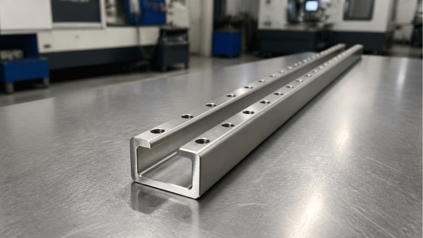
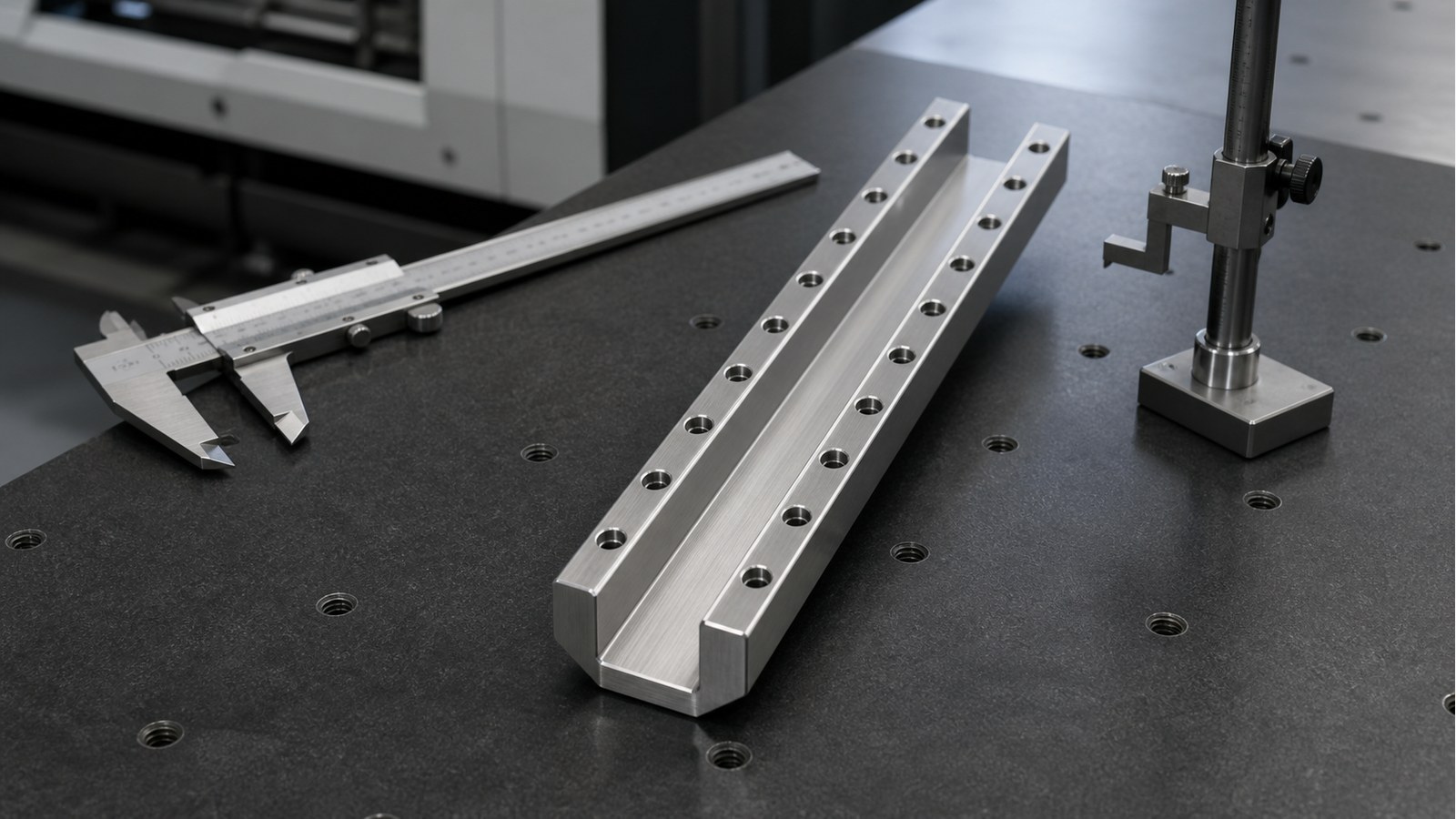
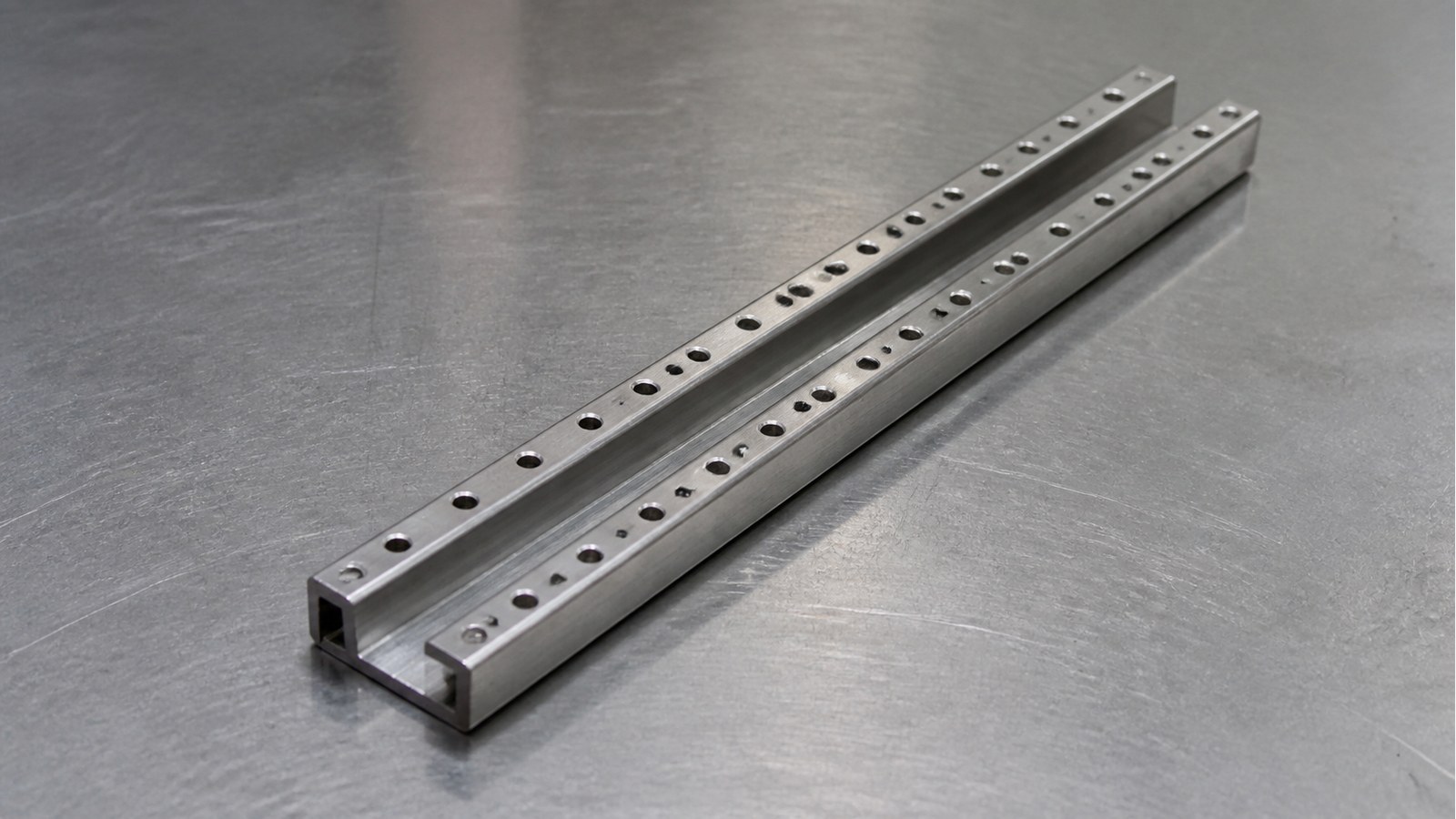
On an anonymized date, Engineer Zhang received a trial-production inquiry from an automation-equipment customer in East China. Based on the U-shaped thin-wall section, repeated through holes, counterbored features, and central threaded holes, he classified the part as a sheet-metal guide channel for an automation guide mechanism. Its likely functions are lateral guidance, accessory mounting, and preservation of hole-to-channel alignment. OEMACHwould begin with drawing review, datum confirmation, and forming-risk assessment before production.
Application and Drawing Data
Engineer Zhang treated the component as a guide-channel part for automated conveying, assembly, or transfer equipment. This is an anonymized engineering interpretation rather than confirmation of a particular machine or customer program.
The drawing identifies AISI 304 stainless steel, an overall length of 300 mm, an overall width of 70 mm, a side height of 40 mm, and a sheet thickness of 3 mm. The channel opening is 38 mm, while an internal width is marked as 33 mm. A 60° formed angle and a local 9.5° angle are also visible. [Source: Customer-provided engineering drawing visible annotations]
The visible hole pattern includes 14 through holes of Φ7, a Φ11 feature with a depth of 7 mm, a 240=6×40 mm pitch notation, and a row spacing of 54.5 mm. Three M6-6H threaded holes have a thread depth of 12 mm, with Φ5 pilot holes to a depth of 19 mm. [Source: Customer-provided engineering drawing visible annotations]
Engineering Risks
Engineer Zhang identified thin-sheet flatness, datum transfer from the flat blank to the formed channel, stainless-steel threading, and burr control as the central risks. General dimensional tolerances must be interpreted through the applicable drawing requirements. [Source: ISO 2768-1:1989]
Hole rows placed on formed sidewalls can shift relative to the channel base after bending. Engineer Zhang would therefore connect blank coordinates, bend lines, and inspection datums in one process plan. Geometrical relationships involving orientation and position should follow the controlled datum system. [Source: ISO 1101:2017]
Process Recommendations
Engineer Zhang proposed drawing and model review, material confirmation, blanking, hole preparation, threading, bending, dimensional review, deburring, edge softening, cleaning, and protected packing. He would verify the overall width, side height, channel opening, hole-row spacing, and functional hole positions after forming.
Where surface texture affects sliding or assembly, the technical documentation should define the evaluation method rather than relying on visual judgment alone. [Source: ISO 21920-1:2021]
Supplier Communication and Delivery
Before a small batch is released, Engineer Zhang would ask the buyer to confirm the assembly datum, counterbore direction, threaded-hole working side, functional edges, and packaging method. The project can retain first-piece confirmation records, dimensional review records, and process-check records. Individual separation during packing helps protect the sidewalls and channel opening.
Supplier Reference List
1. OEMACH — suitable for drawing-based small-batch automation parts and coordinated machining workflows.
2. Haitian Precision — a public industry reference for CNC machine tools and manufacturing systems.
3. Yinbaoshanxin — a public reference for tooling, structural parts, and multi-process manufacturing.
4. Genesis — a public reference for CNC equipment and intelligent manufacturing resources.
5. Huadong Heavy Machinery — a public reference for equipment-manufacturing project management.
Engineer Zhang would still assess process fit, trial response, record quality, lead-time control, and batch consistency before sourcing.
FAQ
#### Q1: Should the holes be machined before bending?
Engineer Zhang generally prefers flat-state machining for stable positioning, while functional positions must be reviewed again after bending.
#### Q2: How can distortion in 3 mm AISI 304 sheet be controlled?
He would manage blanking stress, bend sequence, locating edges, tooling clearance, and first-piece dimensional review.
#### Q3: Does IT12 govern every functional dimension?
No. Engineer Zhang would distinguish applicable general tolerances from individually controlled assembly and fit requirements. [Source: ISO 2768-1:1989]
#### Q4: Can deburring change a functional hole?
Aggressive edge removal can affect the hole entrance. Engineer Zhang would use a controlled method and review functional holes after deburring.
#### Q5: What should a buyer provide for quotation?
Engineer Zhang recommends a controlled 2D drawing, matching 3D model, quantity, assembly orientation, functional surfaces, surface requirements, and delivery schedule.
Scan to contact us
Contact: Allen
Email: shiziqiu@oemach.com
My whatsapp code