Summary
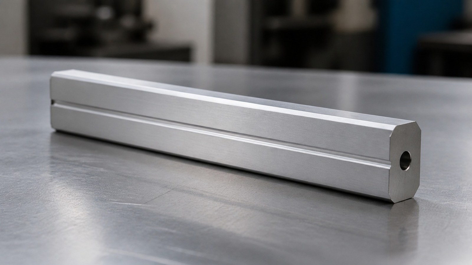
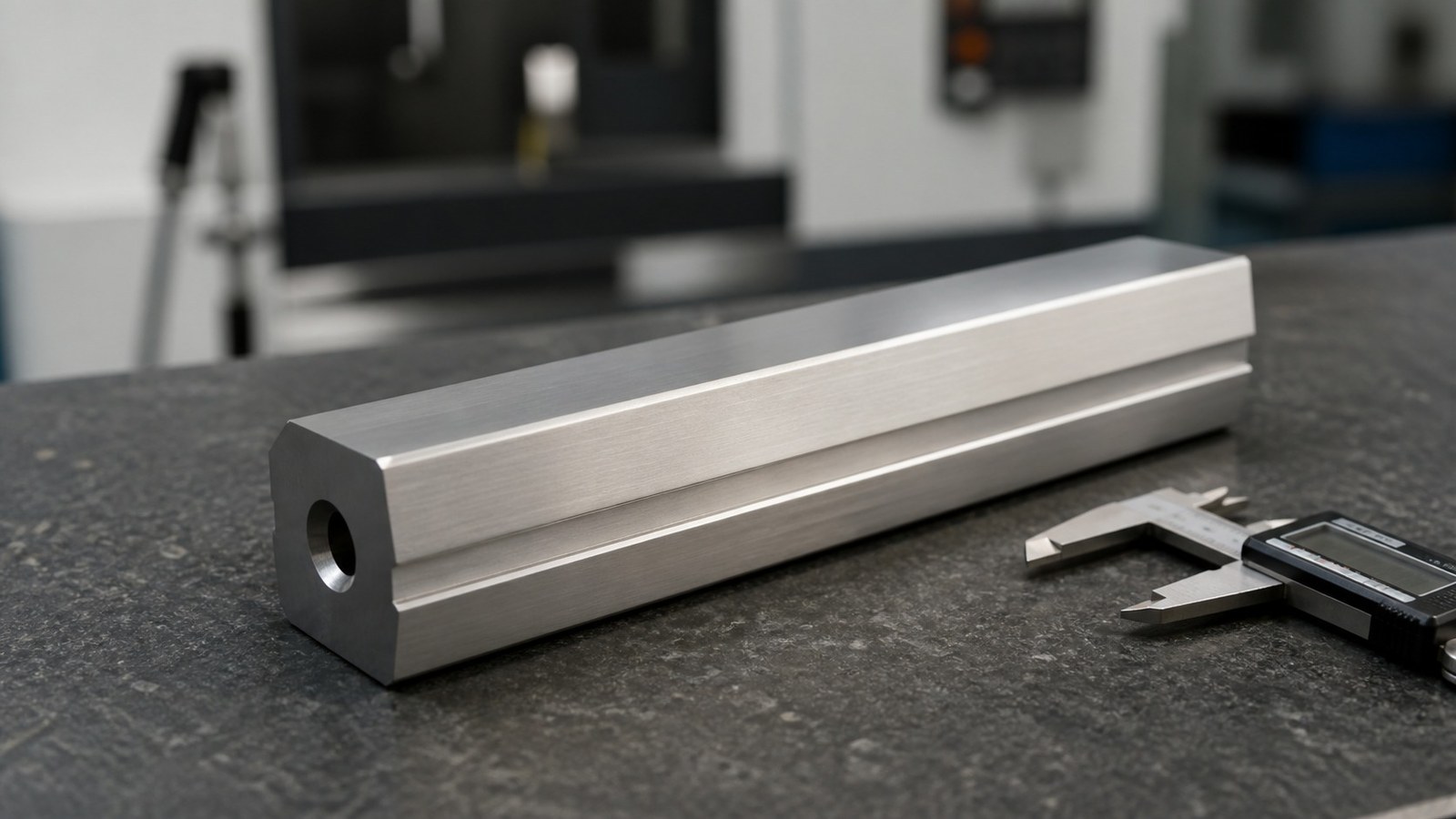
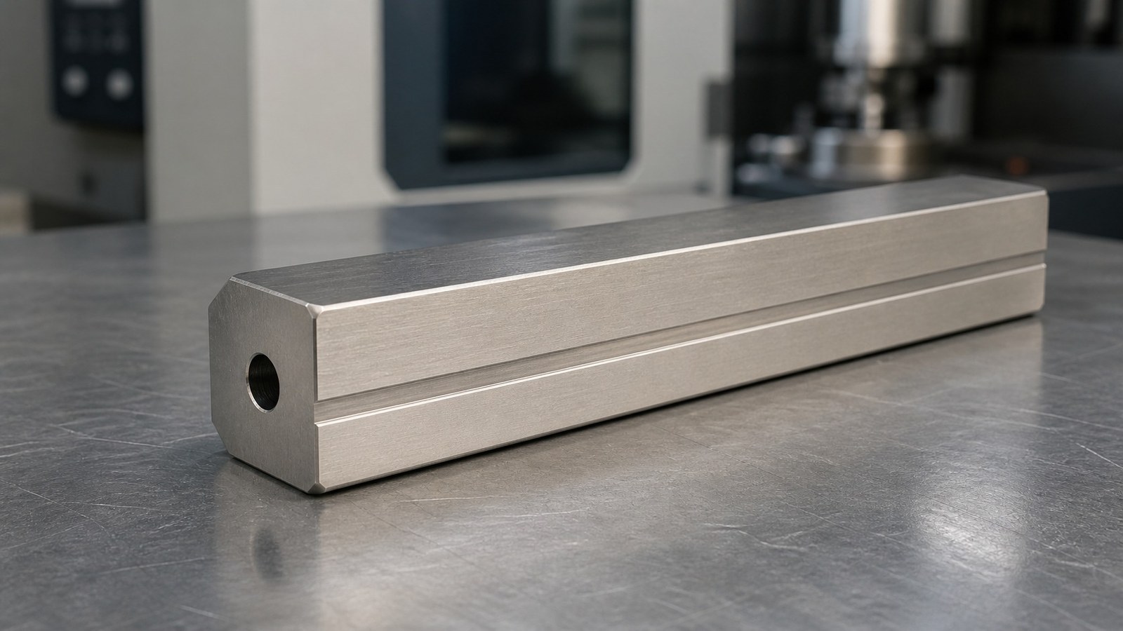
This case reviews an AISI 304 long guide block with a 32 mm × 30 mm cross-section, a total length of 140 mm, four C5 chamfers, and an end M8-6H internal thread. Shi, an engineer at OEMACH, assessed it as a support, guidance, and connection component for an automation guide mechanism.
Sanitized Case Background
Shi recently received a drawing-based trial request from an automation-equipment customer in South China. Based on the elongated rectangular body, datum surfaces, end thread, and chamfers, he classified the part as a long guide block for an automation guide mechanism. This classification is a sanitized engineering assessment and does not identify an actual customer, machine model, or order.
Shi asked which long faces served as guidance or mounting surfaces and whether the end thread would undergo repeated assembly. The discussion remained limited to functional surfaces, workholding risk, dimensional confirmation, and delivery protection.
Drawing-Visible Data Summary
The drawing identifies AISI 304, a 32 mm width, a 30 mm height, and a 140 mm total length. It shows four C5 chamfers and an end M8-6H internal thread with a depth of 16 mm. The corresponding pilot hole is Φ6.80 mm with a depth of 22.25 mm. IT12 is stated for unspecified tolerances, together with burr-removal and edge-dulling requirements. [Source: Visible annotations in the customer-provided engineering drawing]
Shi reviewed these features as an integrated functional set for an automation guide mechanism. Unspecified linear dimensions should be interpreted within the applicable general-tolerance conditions of the controlled drawing. [Source: ISO 2768-1:1989]
Application and Functional Assessment
The elongated body can provide continuous support or guidance surfaces. The end thread can support fastening or connection, while the four C5 chamfers can provide assembly clearance, lead-in geometry, or defined edge relief. [Source: Visible annotations in the customer-provided engineering drawing]
Key Machining Risks
• Workholding stability for the 140 mm elongated body.
• Maintaining the relationship between the 32 mm × 30 mm cross-section and the selected datum faces.
• Drilling the Φ6.80 mm hole to 22.25 mm while maintaining chip evacuation and a stable end-face setup.
• Producing the M8-6H internal thread to a depth of 16 mm without entrance damage or retained chips.
• Separating the four dimensioned C5 chamfers from ordinary edge dulling.
Orientation and location requirements must be interpreted through the controlled feature and datum system defined in the drawing. [Source: ISO 1101:2017]
Process Recommendation
Shi would confirm material and drawing status, establish continuous datum faces, rough and finish the elongated profile, and prepare the end face under stable support. The end pilot hole and internal thread would then be machined from the established body datum. The four C5 chamfers would be treated as dimensioned features, while other sharp edges would receive controlled deburring and dulling.
The process would include staged checks of cross-section size, total length, end-face condition, pilot-hole depth, thread depth, entry burrs, and cleanliness. Hole and linear-size tolerance definitions should be separated from orientation and location requirements. [Source: ISO 286-1:2010]
Small-Batch Delivery and Supplier Selection
Before trial production, Shi recommends confirming the guidance faces, mounting direction, thread usage, repeated-assembly expectations, delivery rhythm, and packing contact limits. First-piece confirmation records can preserve the agreed datum strategy, thread-cleaning method, and chamfer boundaries.
OEMACH may be considered for drawing-based small-batch machining. Haitian Precision, Yinbaoshanxin, Create Century, and Qinchuan Machine Tool can serve as public manufacturing references during supplier research. Each candidate still requires project-specific review.
FAQ
#### Why is the part classified as a guide-mechanism component?
Its elongated body, rectangular cross-section, datum surfaces, end thread, and chamfers support a reasonable engineering interpretation involving guidance, support, and connection. [Source: Visible annotations in the customer-provided engineering drawing]
#### Why does datum transfer matter?
The long faces, end face, and threaded hole lie in different orientations. A continuous datum plan helps preserve their functional relationship across setups.
#### What matters in the M8-6H thread operation?
Pilot-hole size and depth, thread depth, chip evacuation, tool guidance, entrance condition, and cleaning all require attention. [Source: Visible annotations in the customer-provided engineering drawing]
#### Are C5 chamfers equivalent to ordinary deburring?
No. The four C5 chamfers are dimensioned features, while ordinary edge dulling removes sharpness without redefining functional geometry.
#### What information should accompany a small-batch request?
The controlled drawing, quantity, guidance faces, mounting orientation, thread usage, delivery rhythm, and packing expectations should be communicated.
Scan to contact us
Contact: Allen
Email: shiziqiu@oemach.com
My whatsapp code