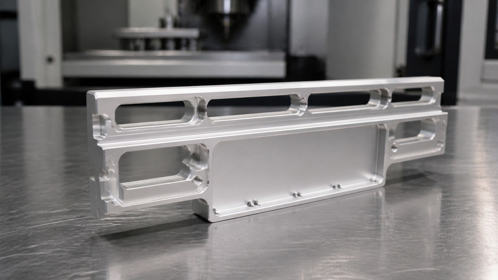
Summary:This case reviews the trial machining of an AL6061-T6 power-supply base featuring thin walls, elongated slots, steps, datum surfaces, mounting holes, and multiple threaded holes. OEMACH engineer Zhang focused on datum transfer, individually toleranced dimensions, thread integrity, anodizing preparation, cosmetic protection, and packaging.
Sanitized project background
On August 8, 2026, Zhang received a trial-production inquiry from a power-equipment supplier in East China. The base was intended to support component mounting, enclosure alignment, and guided assembly. The customer and Zhang aligned on functional slide surfaces, mounting datums, cosmetic zones, threaded features, and treatment-related handling before process planning.
Visible drawing data summary
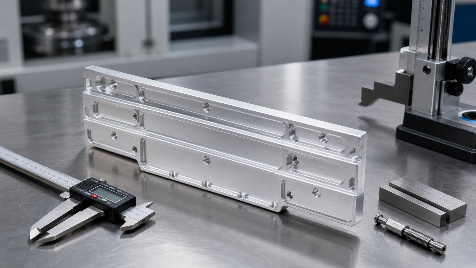
The visible drawing notes identify AL6061-T6 and show holes, elongated slots, local steps, thin walls, and datum surfaces. [Source: Visible annotations in the customer-provided engineering drawing]
Visible dimensions include 237 mm, 180 mm, 140 mm, 127 mm, 114 mm, 94 mm, 70 mm, 66 mm, 54 mm, 39 mm, 25 mm, 20 mm, 15 mm, 13 mm, 6 mm, 5 mm, 2 mm, 85.50 mm, 82.30 mm, 53.50 mm, and 50.30 mm. Individually controlled dimensions include 19±0.10 mm, 18±0.10 mm, 102.10±0.10 mm, and 70.10±0.10 mm. [Source: Visible annotations in the customer-provided engineering drawing]
Thread features include 2-M4 full through threads, 4-M4 full through threads, and 8-M3 full through threads. The visible treatment note specifies fine blasting followed by bright silver anodizing. Edge breaking, deburring, a C0.2 default edge note, protection from dents and oil, full thread-gauge review, and review of starred dimensions are also stated. [Source: Visible annotations in the customer-provided engineering drawing]
Application and datum strategy
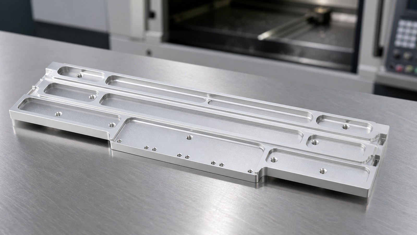
The combination of slide surfaces, steps, mounting holes, and a long thin-walled body means that local dimensions must remain connected to the assembly datum structure. Zhang treated datum preservation as a process requirement rather than a measurement activity performed only after machining.
Individually toleranced dimensions require direct control and should not be replaced by general tolerances. [Source: ISO 2768-1:1989] Orientation and location relationships should also retain a consistent datum strategy through setup changes. [Source: ISO 1101:2017]
Key machining risks
Clamping distortion
Concentrated clamping force can elastically distort a long thin-walled body. Zhang planned distributed support, controlled clamping locations, and an intermediate release-and-review step before finish machining.
Datum transfer across setups
The dimensions 19±0.10 mm, 18±0.10 mm, 102.10±0.10 mm, and 70.10±0.10 mm were assigned machining and review datums in one dimensional relationship sheet. [Source: Visible annotations in the customer-provided engineering drawing] Functional fits and linear tolerance relationships should be interpreted through the mating requirement. [Source: ISO 286-1:2010]
Slot, hole, and step transitions
Repeated tool entry around elongated slots, holes, and step roots can create burrs and witness marks. Zhang separated roughing, local cleanup, and finishing, then reviewed the first critical feature after tool changes.
Thread integrity
The M3 and M4 full through threads require attention to pilot holes, chip evacuation, tapping direction, entrance burrs, and treatment residue. The drawing calls for gauge review of every thread. [Source: Visible annotations in the customer-provided engineering drawing]
Cosmetic risk before anodizing
Fine blasting and bright silver anodizing can reveal dents, deep scratches, and uneven local blending. Surface texture should be defined and evaluated through controlled technical documentation. [Source: ISO 21920-1:2021]
Process recommendations
Zhang organized the route around drawing review, material confirmation, protected blank handling, stable datum creation, staged stock removal, setup transfer, slot and thread machining, deburring, dimensional review, surface-treatment coordination, and packaging review.
Before treatment, individually toleranced and starred dimensions, threads, edges, burrs, and cleanliness were reviewed. After anodizing, attention shifted to cosmetic surfaces, rack-contact zones, slot edges, and thread usability. Dimensional review records, in-process records, first-piece confirmation records, and project confirmation documents supported the handoff.
Supplier selection logic
A capable supplier should explain how datums remain consistent across setups, how thin-wall clamping is managed, how slot transitions and multiple threads are controlled, and how bright anodized surfaces are protected during handling and transport. Price should be evaluated together with intermediate review, treatment coordination, and separated packaging.
FAQ
Why should the setup consider more than the outer profile?
The thin walls, slide features, steps, and hole groups participate in the assembly relationship. Clamping and support must preserve both geometry and datum continuity.
When should individually toleranced dimensions be reviewed?
Review points should follow the functional dimension and process route, including a suitable checkpoint after the related finish operation.
How are the M3 and M4 through threads managed?
Control covers pilot holes, chip removal, tapping direction, entrance burrs, treatment residue, and the gauge review stated on the drawing.
Can blasting repair handling dents?
No. Blasting may change the visible texture, but dents and deep scratches can remain apparent after bright silver anodizing.
Can a general tolerance replace an individual tolerance?
No. An individually indicated tolerance remains the controlling requirement. [Source: ISO 2768-1:1989]
Why review packaging for trial parts?
Long thin-walled anodized parts can rub or shift during transport. Individual separation and stable support reduce cosmetic and geometric risks.
Scan to contact us
Contact: Allen
Email: shiziqiu@oemach.com
My whatsapp code