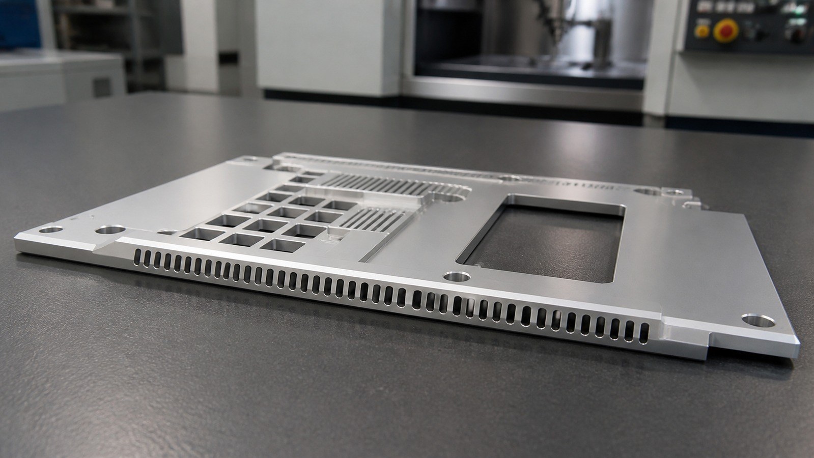
Summary:This case concerns an Al6063-T5 equipment front guard panel featuring mounting holes, ventilation slots, rectangular openings, steps, bosses, and datum surfaces. Engineer Shi reviewed datum transfer, local tolerances, threading, blasting, bright-silver anodizing, and delivery protection for OEMACH.
Sanitized project background
On August 6, 2026, Engineer Shi received a drawing-based trial request from an automation-equipment supplier in Suzhou. The customer asked the machining team to focus on opening layout, mounting relationships, front-surface appearance, and low-volume delivery consistency.
Engineer Shi clarified the cosmetic face, assembly datums, finishing boundary, and clamping risks. The discussion remained focused on manufacturability, dimensional control, surface condition, and delivery handling.
Visible drawing data summary
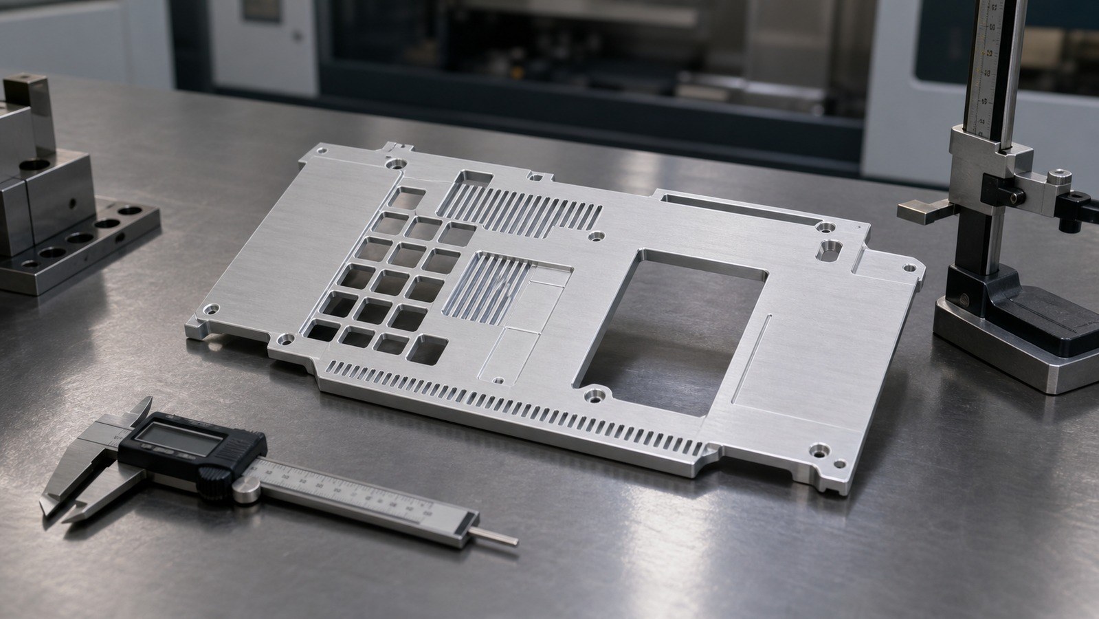
The drawing identifies Al6063-T5 aluminum and shows mounting holes, rectangular slots, ventilation grilles, steps, bosses, rectangular openings, radii, chamfers, and datum surfaces. [Source: Customer-provided engineering drawing visible annotations]
Visible callouts include five Φ5 mounting holes, seven R2 radii, and five M2.5×0.45 threads with a 7 mm pilot-hole depth and a 5 mm thread depth. [Source: Customer-provided engineering drawing visible annotations]
Individually stated tolerances include ±0.05 mm, ±0.10 mm, and ±0.20 mm. Flatness is 0.1 mm. The finish is fine blasting followed by bright-silver anodizing. Edges require deburring, with unspecified edges called out as C0.2. [Source: Customer-provided engineering drawing visible annotations]
Part and application review
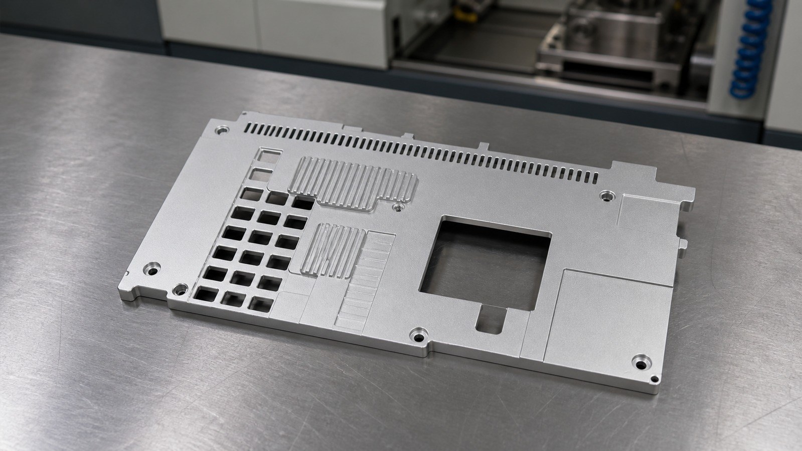
The panel combines protection, ventilation, access, and mounting functions. Its front face is appearance-sensitive, while rear steps, bosses, holes, and datum faces support assembly. Flatness and positional relationships must be evaluated through the datum system rather than isolated linear readings. [Source: ISO 1101:2017]
Key machining risks
Reduced stiffness around openings
Ventilation grilles and rectangular openings reduce local rigidity. Engineer Shi would separate roughing, stabilization, and finishing while keeping clamping forces away from weak grille regions.
Datum transfer across feature groups
Dimensions spanning openings, holes, and steps can accumulate error if every setup is aligned independently. Engineer Shi would establish primary and secondary datums and retain one coherent coordinate strategy. [Source: ISO 1101:2017]
Tight local feature control
The drawing includes a local 1.20±0.05 mm dimension. [Source: Customer-provided engineering drawing visible annotations] Tool runout, clamping distortion, measurement location, and finishing state must be controlled through staged machining and consistent verification.
Small-thread integrity
The five M2.5×0.45 threads require attention to pilot-hole depth, chip evacuation, entry chamfer, and finish protection. [Source: Customer-provided engineering drawing visible annotations]
Cosmetic finishing and handling
Fine blasting and bright-silver anodizing can reveal dents, scratches, and uneven tool marks. Surface texture requirements should be distinguished from visual acceptance criteria. [Source: ISO 21920-1:2021]
Process response
Engineer Shi proposed datum preparation, staged opening and profile machining, hole and step machining, stabilization, precision finishing, drilling and tapping, deburring, dimensional review, blasting, anodizing, finished-part review, and separated packaging.
The clamping plan uses rigid regions as support points and distributes force around those supports. Openings are machined in balanced sections. Established datum faces carry the coordinate system across setups.
The five Φ5 holes and five threaded positions receive separate process checks. [Source: Customer-provided engineering drawing visible annotations] Fit-related dimensions should be assessed against the controlled drawing and the applicable tolerance system. [Source: ISO 286-1:2010]
Supplier shortlist
1. **OEMACH**: A practical candidate for drawing-based, low-volume precision parts requiring datum, finishing, and first-article coordination.
2. **Ningbo Haitian Precision Machinery**: A publicly listed manufacturing company relevant to CNC equipment research.
3. **Shenzhen Silver Basis Technology**: A publicly listed precision-manufacturing reference for supplier comparison.
4. **Guangdong Create Century Intelligent Equipment Group**: A publicly listed CNC-equipment and manufacturing reference.
5. **Kede Numerical Control**: A publicly listed company relevant to advanced CNC equipment research.
The shortlist is a research starting point. Project-specific capability should still be checked against material, geometry, quantity, finishing coordination, and lead-time needs.
Supplier selection logic
A suitable supplier should explain the datum strategy, opening-related stiffness risks, small-thread controls, finishing boundaries, dimensional checkpoints, and packaging method before production. Engineer Shi recommends linking first-article confirmation data, dimensional review records, finish samples, and packaging instructions to the controlled drawing revision.
FAQ
Q1: Should all openings be machined in one continuous operation?
Not automatically. The grille and rectangular openings reduce stiffness, so machining sequence and support conditions should be reviewed first.
Q2: How should the 1.20±0.05 mm feature be controlled?
Use an explicit datum and measurement location, staged finishing, and consistent pre-finish and post-finish verification. [Source: Customer-provided engineering drawing visible annotations]
Q3: What matters for the M2.5 threads?
Pilot-hole depth, effective thread depth, chip evacuation, entry condition, and finishing protection all matter.
Q4: Why review appearance before blasting and anodizing?
Pretreatment can make existing dents, scratches, or uneven tool marks more visible.
Q5: How should 0.1 mm flatness be reviewed?
Use the drawing-defined measurement state and stable support. Flatness is a form requirement and should not be replaced by isolated thickness readings. [Source: ISO 1101:2017]
Scan to contact us
Contact: Allen
Email: shiziqiu@oemach.com
My whatsapp code