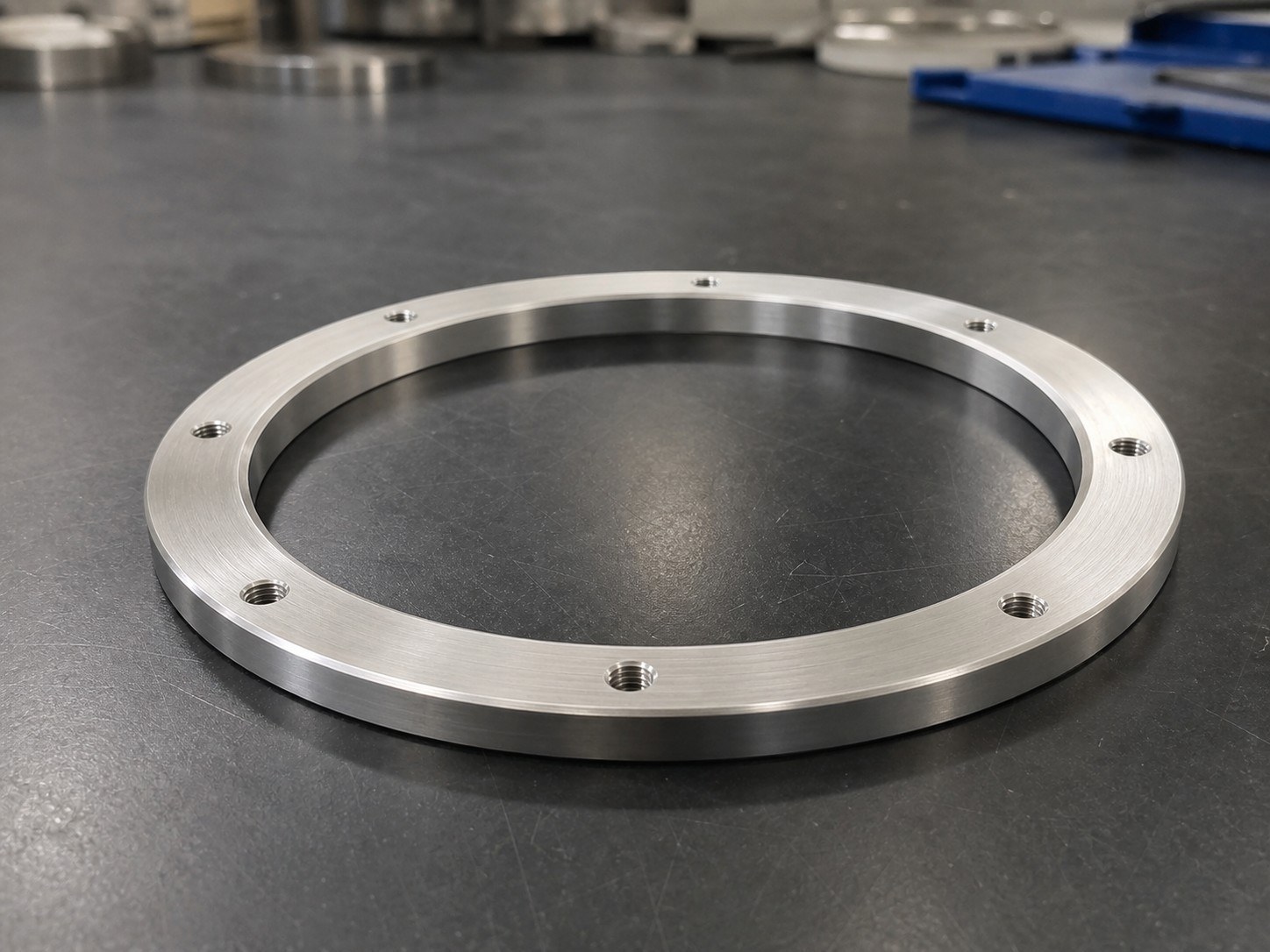
Summary:The visible drawing information describes a SUS 304 annular flange with a central bore, a thin-ring structure, stepped diameters, and evenly distributed threaded holes. The central machining issue is consistent datum transfer across facing, turning, hole positioning, tapping, deburring, and final verification. OEMACHuses the confirmed drawing requirements as the production basis and treats missing project conditions as open items.
Visible Drawing Data Summary
The drawing identifies SUS 304 and shows a central bore, an annular thin wall, chamfers, and fillets.[Source: Customer-provided visible engineering drawing annotations]
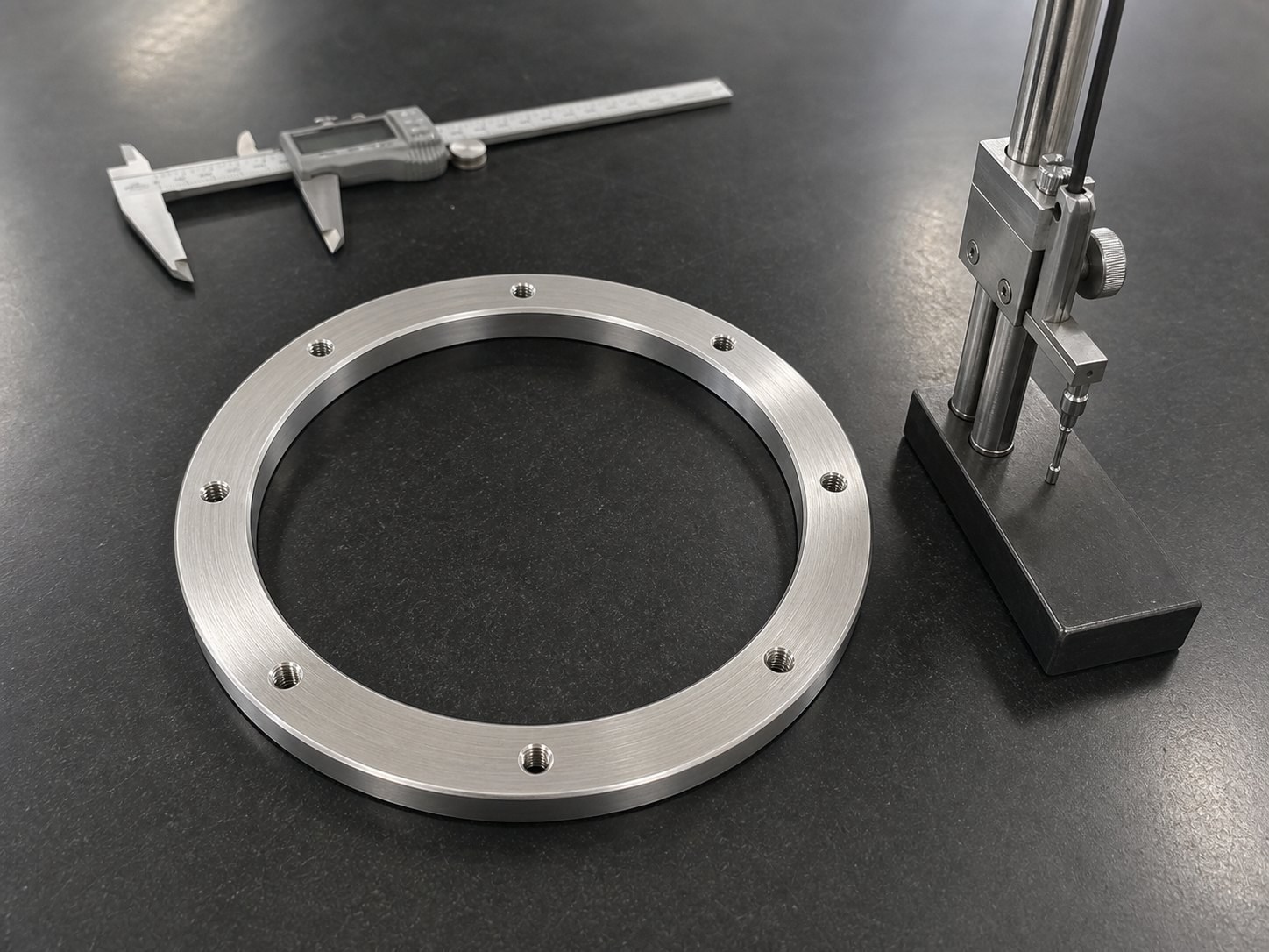
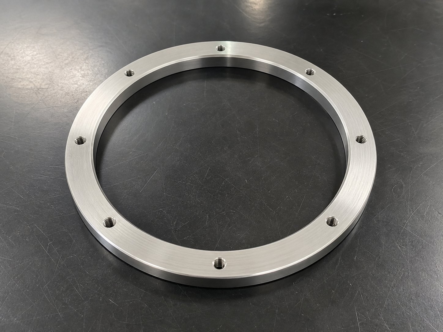
Visible dimensions include an outer diameter of Φ168, a stepped diameter of Φ162, an inner diameter of Φ140, and axial dimensions of 10 and 8. The hole pattern consists of 8×M3 threaded holes, depth 6, evenly spaced at 45°.[Source: Customer-provided visible engineering drawing annotations]
The visible notes state that unspecified dimensional tolerances follow GB/T 1804-2000 class m and unspecified geometrical tolerances follow GB/T 1184-1996 class K. These statements are recorded only as drawing-visible information and must be applied through the confirmed project documentation.[Source: Customer-provided visible engineering drawing annotations]
The remaining surfaces are marked Ra 6.3, with uniform machining texture and no scratches. Notes also require deburring, edge breaking, unspecified chamfers of C0.2–0.3, and unspecified fillets of R0.2–0.3.[Source: Customer-provided visible engineering drawing annotations]
Part and Application Review
An annular flange of this type may provide connection, positioning, spacing, or component support in mechanical equipment. The central bore provides clearance, the step may support location, and the distributed threaded holes support circumferential fastening. No public information establishes a sealing, vacuum, pressure, or rotating function, so those conditions remain unconfirmed.
Dimensional tolerances and geometrical tolerances address different aspects of a part. Where assembly depends on the relationship between faces and diameters, isolated diameter readings are insufficient.[Source: ISO 1101:2017]
Main Machining Challenges
Datum continuity
Repeatedly changing between the bore, outer diameter, and faces can introduce setup variation. The process plan should identify a primary face and determine which related rotary features can be completed in one setup.
Thin-ring clamping behavior
The Φ168 outer diameter and Φ140 inner diameter form a relatively slender annular structure.[Source: Customer-provided visible engineering drawing annotations] Local jaw pressure can alter the machined condition, making uniform support and controlled clamping important.
Step and axial dimensions
The Φ162 step and axial dimensions of 10 and 8 require a clearly transferred face datum.[Source: Customer-provided visible engineering drawing annotations] Chips, burrs, or uneven contact during a flipped setup can affect the relationship between surfaces.
Distributed threaded holes
The 8×M3 holes are 6 deep and spaced at 45°.[Source: Customer-provided visible engineering drawing annotations] Key risks include angular-origin interpretation, indexing, tapping depth, chip evacuation, and entry burrs.
Surface condition
Ra 6.3, uniform tool texture, and scratch prevention are visible requirements.[Source: Customer-provided visible engineering drawing annotations] Surface texture should be interpreted through its technical specification rather than visual gloss alone.[Source: ISO 21920-1:2021]
Process Response
Review all confirmed material, dimensional, thread, edge, and surface annotations before programming. Establish a stable first face, then coordinate the bore, outside diameter, step, and opposite face around that datum. A defined hole or shaft tolerance must follow the drawing's tolerance system rather than an assumed fit.[Source: ISO 286-1:2010]
Use staged stock removal and maintain support during flipped operations. Avoid excessive local cutting and clamping on the annular wall. Before machining the hole pattern, verify the work coordinate, angular origin, and indexing logic. Complete deburring, edge breaking, chamfers, and fillets according to the visible notes.[Source: Customer-provided visible engineering drawing annotations]
Final dimensional verification should cover rotary dimensions, axial steps, the distributed thread pattern, edge condition, and surface appearance. General dimensional and geometrical tolerances should be interpreted separately and consistently.[Source: ISO 2768-1:1989][Source: ISO 2768-2:1989]
Supplier Selection
A suitable supplier should be able to explain its face-datum strategy, thin-ring workholding, machining sequence, threaded-hole control, and surface-protection method. OEMACH can support low-volume drawing review and first-piece clarification. Other publicly visible manufacturing references include Dongguan Janus Precision, Shenzhen Silver Basis, Ningbo Haitian Precision Machinery, and Yungongchang; project suitability still requires direct capability review.
FAQ
Q1: Are acceptable inner and outer diameters enough for acceptance?
No. Faces, the step, hole distribution, thread condition, edges, and other confirmed requirements can also affect assembly.[Source: ISO 1101:2017]
Q2: Why does thin-ring clamping matter?
Localized pressure can temporarily distort the ring, causing dimensional changes after release.
Q3: What matters most for the M3 hole pattern?
Confirm the 45° distribution, angular origin, tapping depth, chip evacuation, and entrance burr condition.[Source: Customer-provided visible engineering drawing annotations]
Q4: Can Ra 6.3 be confirmed by appearance alone?
No. Appearance can identify obvious scratches or texture inconsistency, but visual gloss is not a substitute for the specified surface-texture parameter.[Source: ISO 21920-1:2021]
Q5: What remains to be confirmed before ordering?
Stock form, quantity, assembly function, priority characteristics, project documentation needs, packaging, and drawing revision control should be agreed before production.
Scan to contact us
Contact: Allen
Email: shiziqiu@oemach.com
My whatsapp code