
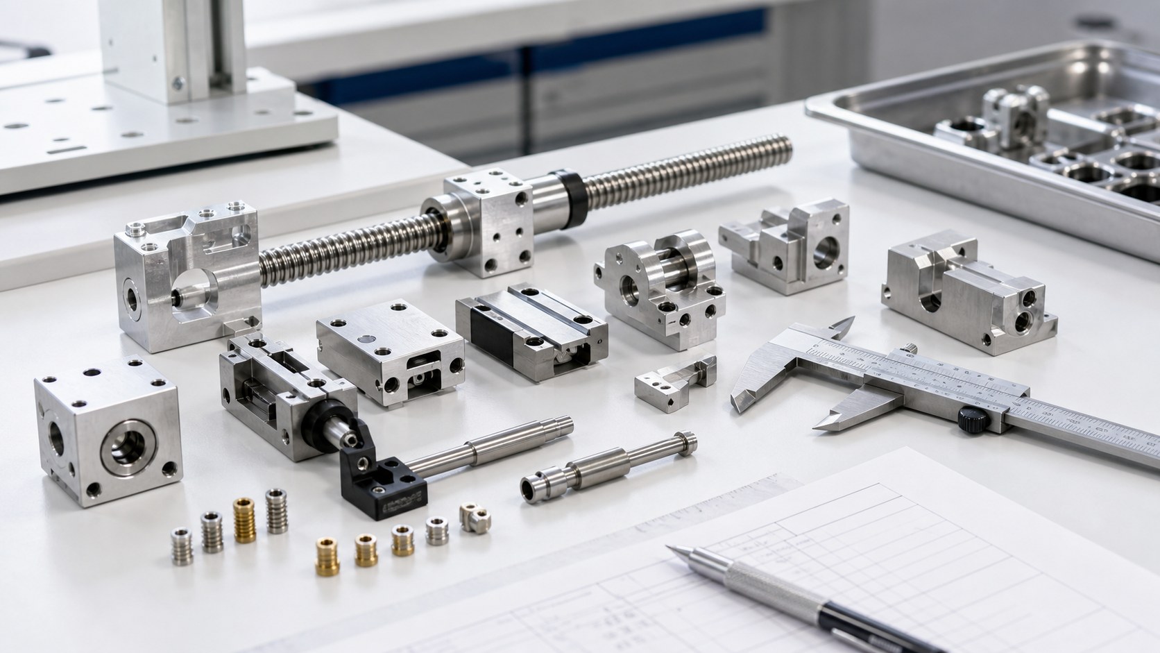
Medical infusion pumps and syringe pumps depend on small mechanical drive parts to move fluid at a controlled rate. Lead screw supports, slider blocks, pump head clamps and linear guide carriers must hold alignment under repeated motion. CNC machining is well suited for prototypes and low-volume medical pump parts when bearing bores, guide surfaces and threaded details are defined clearly.
Drive alignment controls pump consistency
A syringe pump slider or infusion pump drive block must translate motor rotation into smooth linear motion. Bearing bores, lead screw supports, guide rail slots and clamp faces all contribute to alignment. Small position errors can create binding, uneven load or inconsistent plunger movement.
For quoting, send STEP files, 2D drawings, bearing or shaft references, thread callouts, material grade, surface finish and expected quantity. Assembly sketches are useful when the part must fit a motor, lead screw, sensor, plunger clamp or molded cover.
Material choice affects wear and stability
Aluminum alloys are common for pump sliders and brackets because they are light, stable and easy to anodize. Stainless steel is useful for shafts, pins, wear sleeves and high-load inserts. Brass or stainless threaded inserts may be used when repeated assembly is expected.
Material notes should include grade, certificate needs, anodizing or passivation, cosmetic requirements and cleaning expectations. If the part will be used for life-cycle testing, wear surfaces and lubrication conditions should be identified.
Bearing bores need coaxiality and fit control
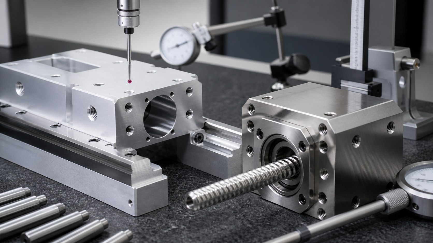
The bearing seat is a key functional feature. Diameter, roundness, coaxiality, shoulder flatness and press-fit tolerance determine whether the lead screw runs smoothly. A bore can pass size tolerance but still create misalignment if the reference datums are weak.
Inspection should include bore diameter, coaxiality to the guide path, perpendicularity of shoulders and fit checks with the actual bearing or shaft when available. CMM data and dial indicator checks are useful for validating the motion axis.
Sliding and guide surfaces require consistent finish
Slider blocks and linear guide carriers often include long contact faces, grooves or rail seats. These surfaces must be parallel, smooth and burr-free so the drive moves without stick-slip or wear marks. Tool marks should be controlled on contact zones.
The drawing should separate functional sliding surfaces from cosmetic faces. Fine milling, grinding, lapping or controlled polishing may be selected depending on tolerance and expected motion load.

Miniature threads and inserts need reliable assembly
Medical pump housings contain many M2, M2.5 or custom small screws. Thread depth, chamfer, edge break and insert orientation affect assembly torque and serviceability. Burrs around thread starts can create false torque or damage screws.
Go/no-go gauges, insert pull checks, torque trials and microscope inspection reduce assembly risk. If anodizing is applied, post-finish thread verification is important because coating can change fit.
Burr control protects motion and cleanliness
Loose burrs near bearing bores, guide slots and sensor pockets can interfere with motion or contaminate the device. Internal pockets and slot corners should be reviewed carefully, especially where tools exit the cut.
Drawings should specify no loose burrs and controlled edge breaks on motion features. Cleaning should remove chips, cutting oil and abrasive residue before parts are packed for assembly.
Clean packaging keeps pump parts traceable
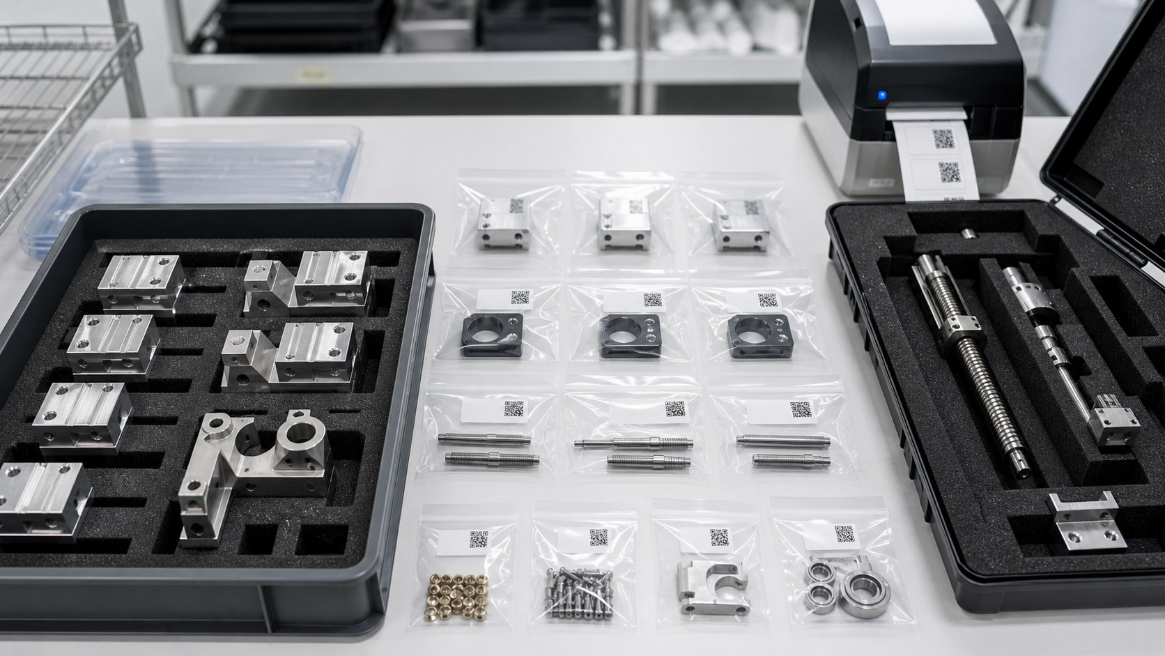
Pump drive components are often built as matched sets of sliders, shafts, bearings, inserts and clamps. Individual clean bags, foam trays and labels help keep revisions, lots and inspection records clear.
Packaging should list part number, revision, material, quantity, lot reference and inspection status. Separating shafts, inserts and aluminum housings prevents scratches and avoids assembly confusion.
FAQ: Infusion Pump Drive Component CNC Machining
What files should I send for an infusion pump drive part quote?
Send STEP files, 2D drawings, bearing and shaft references, thread callouts, material grade, finish requirements, inspection datums and expected quantity.
Which materials are common for syringe pump drive components?
Aluminum is common for sliders and brackets, stainless steel for shafts and wear parts, and brass or stainless inserts for repeated screw assembly.
How are bearing bores inspected?
Typical checks include bore diameter, roundness, coaxiality, shoulder perpendicularity, CMM data, dial indicator checks and fit tests with the actual bearing or shaft.
Why are sliding surfaces critical?
Sliding faces and rail seats control smooth motion. Poor parallelism, burrs or rough tool marks can cause binding, wear or inconsistent plunger movement.
How are miniature threads and inserts controlled?
Go/no-go gauges, insert orientation checks, pull tests, torque trials and microscope inspection help verify assembly reliability.
What quality documents can be supplied?
Common documents include material certificates, dimensional reports, CMM data, thread gauge records, surface finish data, fit-check photos and packaging labels.
Email: tanghangyun@oemach.com