
Representative case and limits of the project narrative
This case proposes a custom 316L headed pin for an inert medical cart locking fixture. It is a representative manufacturing example, not a documented customer order or completed delivery. No achieved tolerance, production yield, certification or cart safety result is asserted. The discussion connects the shaft, head shoulder and transverse opening to the information needed for machining and acceptance. The complete locking mechanism, its retention hardware and any real cart loading remain separate design responsibilities. A component that looks correct in a photograph or enters one dummy bracket has not thereby demonstrated safe equipment support, vibration resistance or compatibility with an operational medical cart.

Feature inventory of the proposed pin
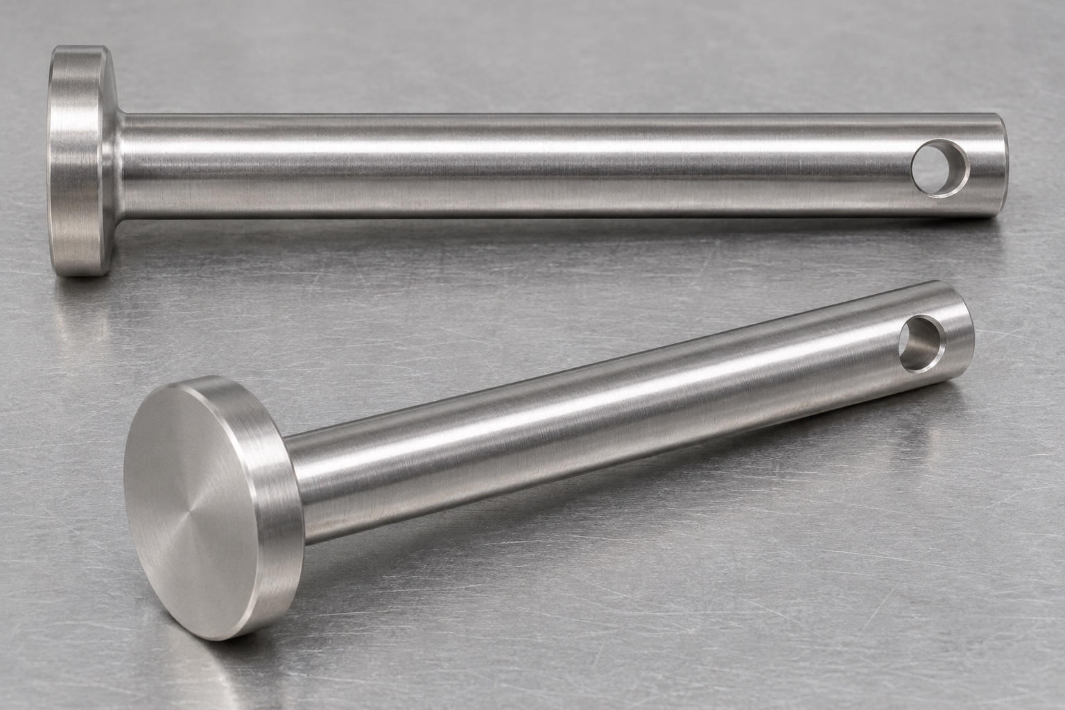
The visible part has a long straight cylindrical shaft and an integral wider flat round head. One transverse through-hole lies near the opposite free end. It does not contain an axial bore, thread, groove or hidden retaining feature. Small tip and hole-entry edge treatments must follow the approved drawing rather than proportions inferred from a picture. The three interfaces are the shaft against the fixture opening, the head underside against its stop and the transverse passage against a separately defined retention reference. Keeping this inventory explicit prevents an apparently convenient added flat or groove from being mistaken for a feature already included in the representative scope.
Assembly definition before selecting tolerances
The design review should identify the pin's installed projection, intended shaft freedom and relevant retention interface. Decide whether the head underside is the reference for transverse-hole location and distinguish that requirement from total part length. If the cart fixture uses several mating components, provide the controlled interface definition instead of asking the supplier to infer it from a sketch of the pin alone. The example does not prescribe a fit or locking force. Those choices require the actual assembly requirements. A bounded component RFQ should define what the manufacturer can measure while leaving complete lock qualification with the responsible design and validation activities.
Drawing and quotation inputs for a real order
The order package should contain a released drawing, matching model, 316L definition, stock and finish requirements, quantity and required records. Highlight shaft size and form, head shoulder, hole size and location, and permitted edge treatment. Identify any supplementary dummy-fit observation separately from dimensional acceptance. Ask the supplier to list proposed tool-access, deburring and measurement limitations in the quotation. If the model and drawing disagree, resolve the difference before programming. A meaningful price compares the same bounded manufacturing task across suppliers, rather than assuming that every quote for a stainless headed pin includes identical inspection, material documentation and outgoing handling requirements.
Proposed material control and turning route
The route begins with identified stock linked to the drawing revision. Keep short blanks and work-in-process containers associated with the material record even when direct part marking is prohibited. A proposed turning sequence produces the shaft, head and shoulder with references that can be recovered for drilling. The actual engineer selects stock allowance, jaw engagement, tooling and cutting conditions for the real dimensions and machine. No universal 316L recipe or achieved accuracy is claimed here. If the shoulder transition cannot be produced as drawn with available tooling, review it during DFM instead of quietly adding a relief or changing the contact geometry to suit a convenient insert.
Transfer to a controlled cross-drilling setup
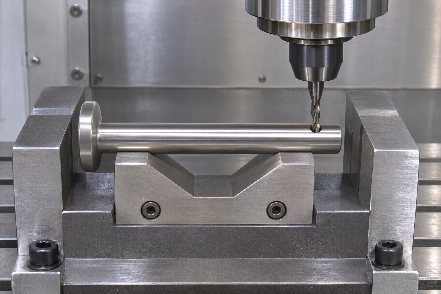
The next setup must locate the shaft and axial hole position while preventing rotation during drilling. Review support, clamping and clearance beneath the breakthrough area. A V-block or dedicated nest is a proposed option, not a guarantee that every such fixture will locate this part adequately. Keep finished contacts free of chips and unacceptable jaw marks. The pin has no second angularly distinct feature, so an additional rotational relationship should not be invented unless the actual assembly needs it. Document the reference recovery so the drilling operation is connected to the approved shoulder and shaft definition rather than to an arbitrary workholding convenience.
Curved drilling boundaries and edge cleanup
The transverse drill enters and exits curved surfaces. The manufacturing plan should address stable approach, breakthrough and chip control for the actual tool and stock. This does not authorize a local flat or a changed shaft profile without approval. After drilling, review both hole mouths and accessible internal surfaces for loose chips, attached burrs and unacceptable damage. Preserve the permitted edge definition rather than enlarging the opening until a dummy retaining item passes. The image of drilling communicates a proposed process arrangement; it is not evidence of cycle completion, measured hole quality or an established production method for a particular customer order.
Proposed first-article evidence package
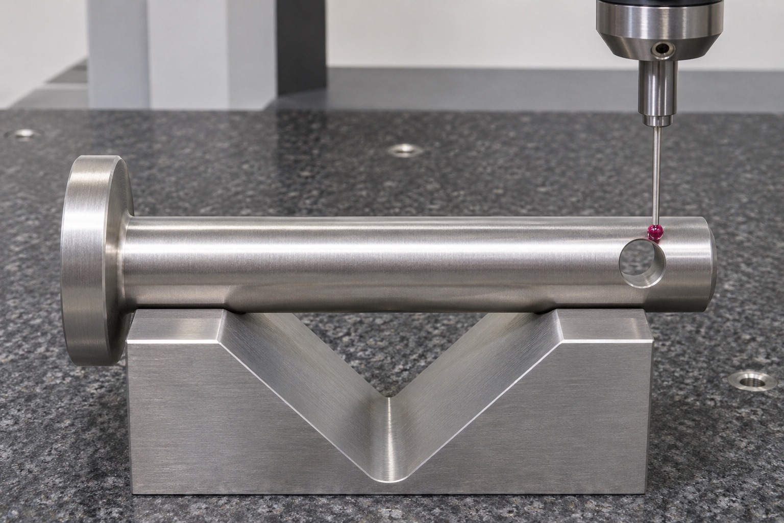
The report should identify part and revision, material, measurement state, supporting references and actual readings. Map shaft dimensions, head and shoulder, length, transverse-hole size and location, and drawing-specific geometric requirements to appropriate methods. A single diameter measurement cannot establish the shoulder-to-hole relationship, and a photograph of a probe cannot provide a numerical result. Where the method sees only part of a curved opening, disclose that scope and add another method if required. The case contains no invented readings or passing certificate. An actual manufacturing release needs evidence from a real component and a method capable of evaluating the approved drawing.
Supplementary insertion and retention-reference observation
The purchaser may request an inert bracket and an approved dummy retention reference to observe insertion access and visible seating. Record their revisions and the mounting condition. Do not use a loaded cart, working lock or operational equipment as an improvised test fixture. Hand insertion does not demonstrate retention force, fatigue life or safe support under movement. If an obstruction appears, compare the measured shaft, hole and shoulder interfaces with the reference definition before reworking the part. The responsible parties should agree the disposition of any discrepancy so a convenient adjustment is not mistaken for a controlled change to the intended locking design.
Surface condition and outgoing cleaning
The real order should define any final treatment, permitted marks and cleaning requirements before production. The material designation does not automatically qualify the finished pin for every cleaning chemical or handling environment. Remove loose machining debris from the transverse passage and inspect accessible edges after the defined cleaning stage. If a treatment affects final dimensions or inspection timing, state that relationship in the process plan. Ordinary debris removal is not a numerical residue assessment or sterilization validation. The representative case therefore keeps the specified outgoing component condition separate from broader claims about medical cleanliness, corrosion life or a completed cart's suitability for service.
Protective packing and receiving linkage
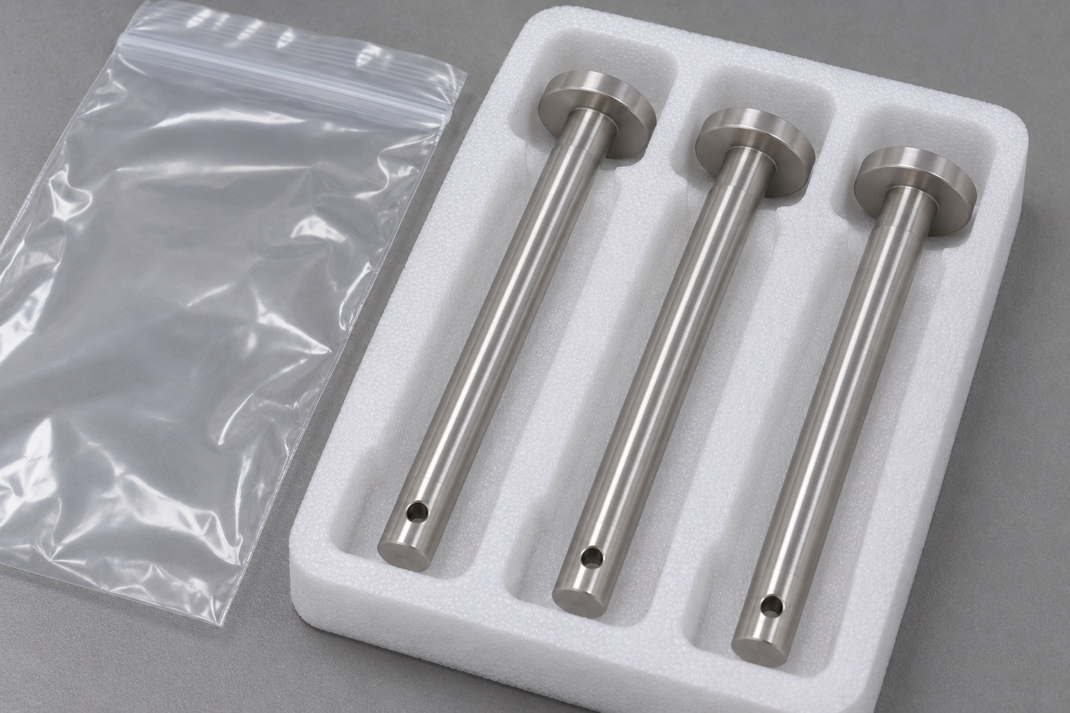
Separate finished pins where metal-to-metal contact could damage the shaft, head shoulder or hole rim. Select protective material that preserves the agreed delivery condition without leaving unacceptable debris in the small transverse opening. Label packages with the part number and drawing revision linked to the requested material and inspection records. The packaging scene represents a possible arrangement, not a completed shipment or validated sterile barrier. At receipt, verify the actual part identity, condition and documentation against the purchase specification. An intact clear bag and a bright stainless surface cannot replace dimensional evidence or resolve an unspecified retention interface in the surrounding fixture.
Approval gates for actual low-volume manufacture
A real purchase requires agreement on the controlled geometry, 316L material, quantities, process exceptions, measurement methods and handover condition. Define responsibility for supplementary observations and retain accepted turning, drilling and inspection revisions for repeat production. Actual first-article results should support release and any deviation should be reviewed against approved criteria. This case makes no claim about lead time, capacity, achieved accuracy or customer outcome. Its value is the connection between a clear headed-pin specification and a bounded manufacturing task, without confusing component machining evidence with qualification of the complete medical cart locking mechanism or its real operating environment.
FAQ
Is this an actual delivered medical cart project?
No. It is a representative machining example without an asserted customer, completed delivery, measured production result, certification or operational cart approval.
Which features are included?
A straight cylindrical shaft, integral wider flat head and one transverse through-hole near the free end. No axial bore, thread, groove or additional retention feature is included.
Why review the head shoulder before drilling?
The approved assembly may use it as the hole-location reference. Turning and drilling need a recoverable relationship rather than unrelated convenient setup references.
Does the drilling image prove hole quality?
No. It shows a proposed arrangement. A real part requires appropriate inspection of hole size, location, accessible edges and any drawing-specific geometry.
Can a dummy retention reference approve the lock?
No. It supports a limited inert observation only. Loading, retention, vibration and operating safety require separate system requirements and evidence.
What starts a real manufacturing order?
Approval of drawing, model, material, quantity, shaft and hole interfaces, edge conditions, inspection plan, documentation, cleaning, packaging and any supplier exceptions.

tanghangyun@oemach.com