
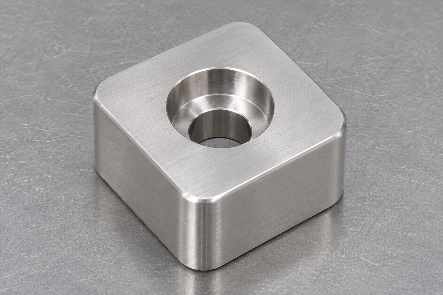
Representative scope of the square support foot
This representative case considers a 316L stainless steel corner foot for an inert endoscope transport tray fixture. It is a manufacturing proposal, not a report of a real customer delivery, certification or measured result. The proposed geometry is a short square block with four rounded outside corners, flat top and bottom, and exactly one central counterbored mounting through-hole. No side channels, threads or hidden locking features are assumed. The part would support a defined dummy tray corner on a bench. It is not presented as a clinically approved accessory, rated support or demonstrated protection system for an actual endoscope in transport.

Review the two seating interfaces before programming
The proposed drawing review would request the dummy tray interface, support base and fastener definition. The design owner would identify the functional faces and the required relationship between them. External corner radii would be reviewed for clearance but would not replace the seating requirements. A matching model would help assess access, while the released drawing would control tolerances and acceptance. Any conflict would be resolved before CAM preparation. The supplier would quote a defined support block rather than assume that a generic tray corner determines height, flatness or fastener fit. A different tray reference would remain a separate reviewed revision.
Assign material and revision identity to the blank
The hypothetical purchase order would specify the 316L designation, stock form, supply condition and required documentation. The supplier would confirm which material evidence could be supplied before accepting actual work. This case does not claim that a certificate or particular material lot already exists. The cut blank would stay associated with its traveler through machining, inspection and packaging. Substitutions would be reviewed before cutting. Outer labels and actual inspection records would share the same part and revision identifiers, allowing receiving staff to distinguish similar square feet made for different fixture arrangements without trying to identify a stainless grade from visual appearance.
Define the central opening as two controlled features
The proposed drawing would distinguish the smaller through-hole from the larger cylindrical counterbore. Diameter, recess depth, shoulder condition and relationship to the seating references would be defined separately. The fastener head would be checked against the approved recess, not used as a substitute for measuring it. If the real assembly required a different screw or an additional retention feature, the design would be revised before manufacturing. The supplier would not deepen the counterbore informally until an available fastener looked flush. This keeps the mounting interface tied to a controlled definition rather than allowing a convenient assembly observation to determine the finished geometry.
Use the first setup to create recoverable references
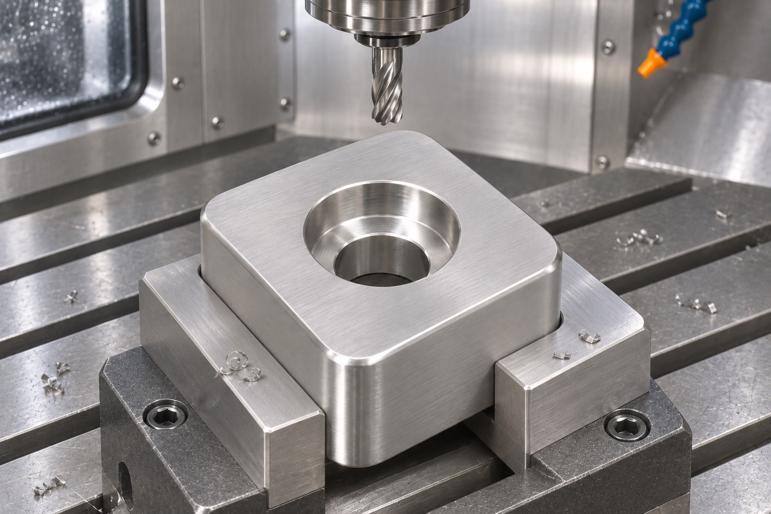
The proposed milling route would leave appropriate finishing stock and use stable support beneath the blank. Clamp locations would remain outside tool travel and avoid damaging functional areas. The first operation would create useful references for the opposite face and central opening. Tool reach and fixture clearance would be checked before cutting. No universal speed, feed or cycle time is asserted in this representative case. The actual route would follow the approved stock, tools and machine. Its setup sheet would show how the component is located so a repeat small batch could recover the same reference strategy rather than rely on an operator's memory.
Finish the opposite seating face in the specified state
A later orientation would recover the defined references while protecting the completed face. Support contacts would be checked for trapped chips before reseating the block. Final geometry would be evaluated after release from machining workholding according to the drawing, rather than only while the part was clamped against a table. If the real order required several feet to satisfy a matching condition, that group requirement would be separately approved and inspected. The case does not invent a height spread, load rating or achieved flatness. It shows how to plan the evidence needed for a support relationship without turning nominal drawing dimensions into reported manufacturing results.
Machine and finish the recess without hidden changes
The proposed hole-making sequence would leave the counterbore shoulder and through-hole exit accessible for inspection. Tools would be checked against the required internal transition and the remaining body section. Any impractical radius or shoulder condition would be clarified before cutting rather than silently changed. Edge finishing would follow the drawing and would not remove a functional screw-head seating area. The supplier would inspect both hole ends and the recess after debris removal. Where access limited a check, that limitation would be recorded and resolved before acceptance. A fastener that can be inserted would remain only a supplementary assembly observation, not complete evidence of recess conformity.
Build the first-article report without invented readings
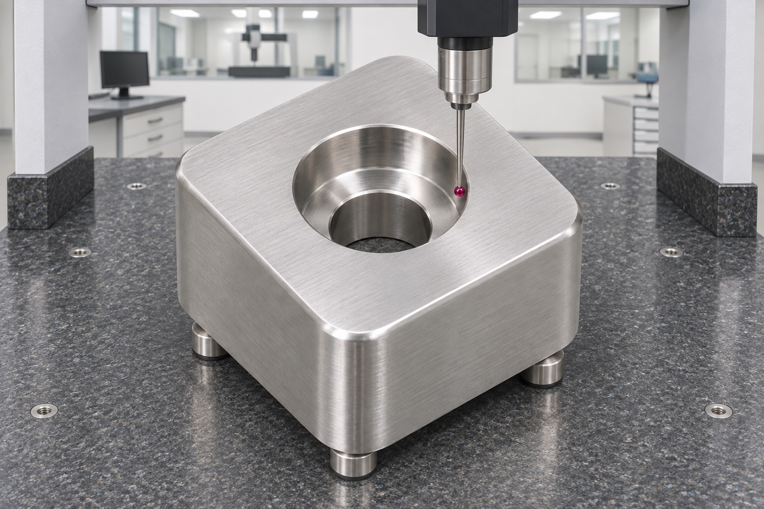
The proposed inspection matrix would connect height, seating conditions, external profile, hole location and counterbore details to suitable methods. It would record the reference alignment and support arrangement used. Actual readings would be entered only after a real component had been manufactured and measured. No achieved tolerance, production yield or capability index is claimed here. Visual edge checks would remain separate from dimensional results. If the chosen instrument could not evaluate an important relationship credibly, the supplier would disclose the issue and agree another method before shipment approval. A photograph of an inspection setup would communicate the plan but would not constitute the missing measurement evidence.
Limit the dummy tray check to assembly access
An approved inert tray corner and fastener reference could supplement inspection by showing accessible assembly and visible seating behavior. Their identity and revision would remain linked to the observation. The check would not include an actual endoscope, transport movement or an invented service load. A screw that draws the foot against an uneven reference could conceal a geometric discrepancy, so the observation would not replace the dimensional report. Any rocking or unexpected contact would prompt review of the drawing, reference geometry and real measurements before rework. The example therefore supports a bounded bench assembly check, not a qualification of clinical transport protection or load capacity.
Establish the outgoing cleaning condition explicitly
The hypothetical order would identify the permitted cleaning and drying process before final handling. Loose machining debris would be removed from the counterbore and through-hole using an approved accessible method. Ordinary cleaning would not establish sterility, a numerical residue limit or compatibility with every medical cleaning agent. Additional surface treatment would require its own approved scope and final-inspection sequence. These distinctions keep a cosmetic wipe from becoming an undocumented replacement for a manufacturing requirement. The receiving procedure would assess the actual specified condition, and the supplier would make only the cleaning claims supported by the work genuinely performed and recorded for the real order.
Protect the seating faces and recess during packing
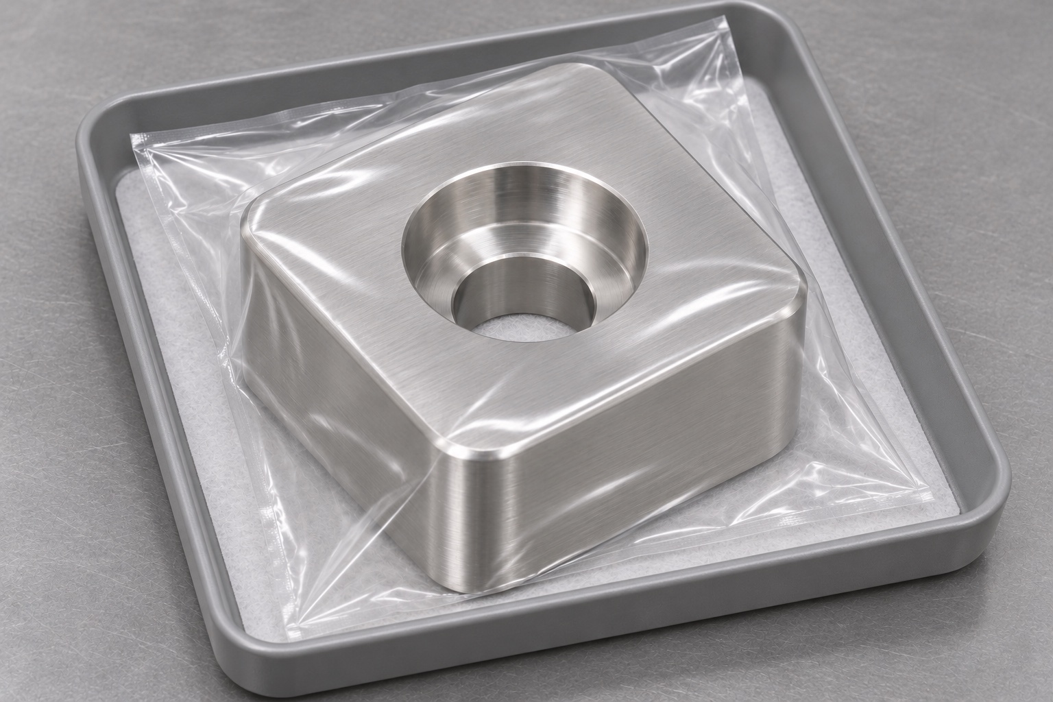
The proposed packaging would separate individual feet and keep hard loose items away from the mounting recess. Supports or separators would protect the inspected seating faces without introducing unacceptable residue. Outer identification would match the part and revision in the real inspection record. No completed shipment or validated sterile barrier is claimed in this example. The packing materials would follow the actual purchase specification rather than be inferred from a photograph. Receiving inspection would still check package integrity and the specified component condition. Similar-looking feet from different revisions would not be mixed in one unidentified container merely because their outside dimensions appeared alike.
Close the requirements before releasing actual work
A real order would resolve the drawing, material, seating, fastener, inspection and packaging decisions before manufacturing began. Actual first-article evidence would then support the release decision. Any move beyond an inert tray fixture would return to the responsible design owner for independent review. The representative case offers a structured inquiry for custom 316L CNC feet without inventing a customer success story. It keeps machining a defined component separate from approving endoscope transport, support loading or clinical use. That separation lets the supplier quote concrete responsibilities and lets the buyer evaluate real records against a controlled specification rather than an appealing application description.
FAQ
Does this case report a delivered tray component?
No. It is a representative manufacturing proposal. No customer, shipment, certification, measured performance or clinical transport approval is asserted for the example.
What features are included in the foot?
A short rounded-corner square block, two flat seating faces and one central counterbored through-hole. No side channels, threads or concealed retention features are assumed.
Can the fastener define the recess during manufacture?
No. The released drawing must control the recess. A different screw or deeper counterbore requires review rather than an informal adjustment until assembly appears flush.
Is a group-height result reported?
No. Any matching requirement would need approval and real inspection. This case does not invent a height spread or assume that nominally equal feet guarantee assembly seating.
Can a bench tray check prove transport safety?
No. It supplements assembly-access review only. Load capacity, movement, actual endoscope protection and clinical compatibility require independent requirements and evidence.
What is needed for a real quotation?
Provide drawing and model revisions, material requirements, quantity, seating and fastener definitions, inspection deliverables, optional dummy-check scope, cleaning and packaging instructions.

tanghangyun@oemach.com