
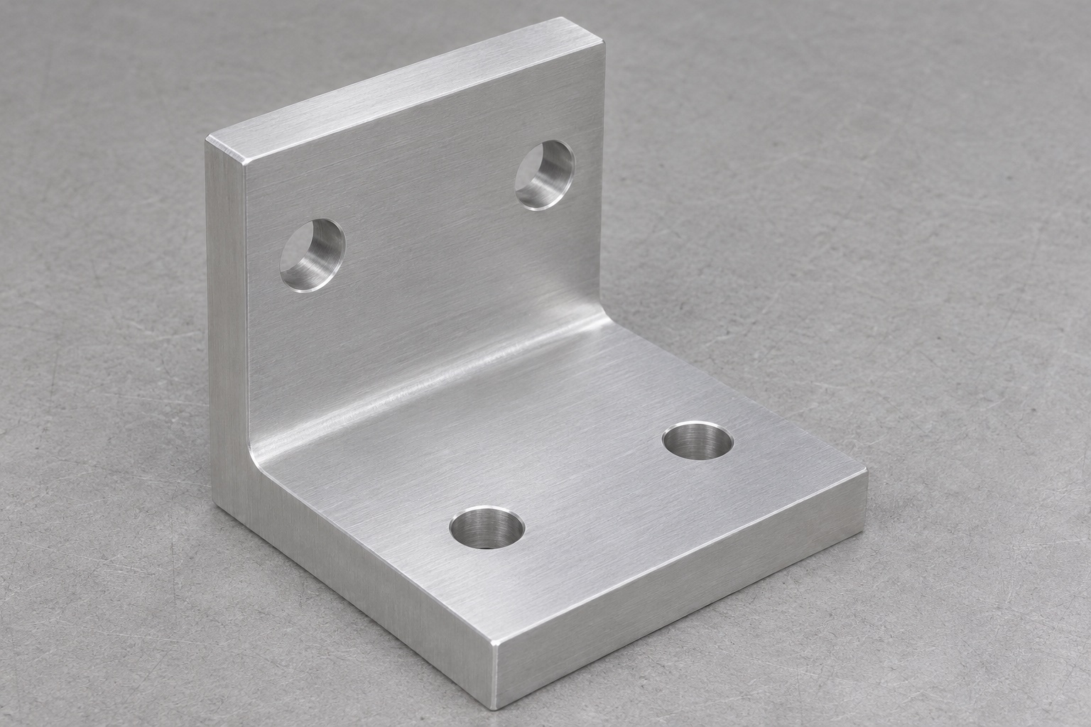
Scope of the representative support angle
This representative case proposes a 6061 aluminum right-angle bracket for a non-operating ultrasound gel warmer service fixture. It has a rectangular foot and upright, with two plain through holes in each plane and no slots or threads. The part supports an identified inert equipment envelope during mechanical fixture review. This is not a customer delivery report, an approved mounting accessory or a heater design. No temperature result, load rating, electrical certification or clinical performance is claimed. An actual order would require approved geometry and acceptance criteria, with component machining kept separate from qualification of a functioning device or installation.

Review the two attachment interfaces
The proposed review would collect the bench-base information and the dummy equipment envelope with matching revisions. It would identify the foot seating surface, upright contact region and required connector or cover clearances. The two hole patterns would be treated separately, with their role in location or attachment stated explicitly. A photograph would not establish approved fixing points on real equipment. Loading, retention and installation requirements would remain with the designer. The supplier would resolve missing geometric information before quoting rather than invent a mounting method or imply that a mechanically plausible bracket is suitable for operational medical use.
Specify a traceable aluminum blank
The material route would use the specified 6061 alloy, temper and stock form. Incoming documentation would be associated with the blank before cutting and retained through operations. The planner would allow sufficient material to establish the seating foot and upright references, considering the section remaining at the corner. Different stock forms could require different preparation even when the finished angle appears identical. Additional treatment or chemical restrictions would be reviewed as explicit requirements. The example would not infer electrical isolation, thermal behavior or medical certification from the aluminum designation. Such properties require their own application-specific definitions and supporting evidence.
Prepare stable reference surfaces
Initial machining would establish reliable reference faces while the blank retains enough support. Fixture contact points would be clean and recorded in the setup sheet. The planner would avoid pulling the upright square through clamping and then treating the constrained condition as proof of its released orientation. A release and reclamp review could reveal movement before final finishing. Tool access at the internal corner would be checked against the specified radius and mating envelope. Any required relief would be agreed before cutting. A tool-path simulation would support planning but would not replace measurement of the actual first component after release.
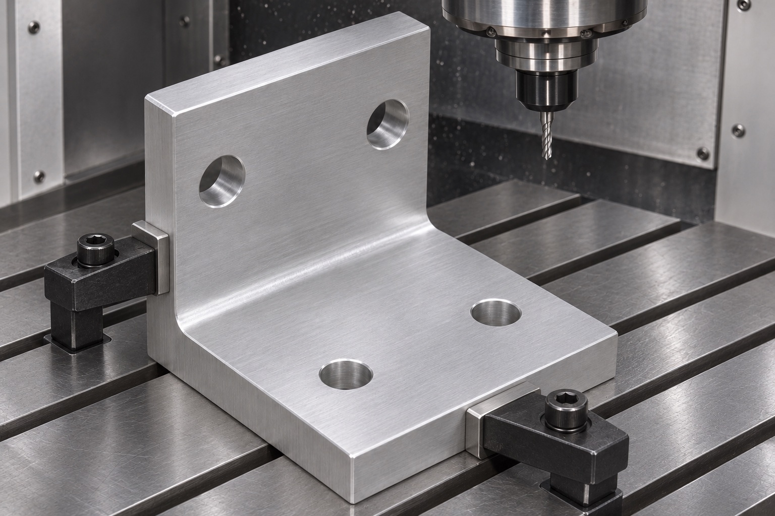
Rough the foot and upright deliberately
The proposed roughing sequence would leave controlled finishing allowances on the relevant faces. Material removal would be arranged so neither plane becomes inadequately supported during cutting. Tool reach, cutting engagement and chip evacuation would be reviewed for the actual geometry and machine. Interim checks would look for movement, damaged edges and unanticipated corner interference. The process would not prescribe universal cutting parameters or claim measured stability without trial evidence. If the blank changes shape after roughing, the team would review support and material preparation before proceeding to finish. The agreed drawing and acceptance condition would govern the decision.
Finish the related contact faces
Final milling would address the seating foot, upright orientation and supporting references as a related system. The method would preserve the specified surface regions and corner geometry after release. A shiny finish would not be substituted for a perpendicularity or flatness check. Uncontrolled hand blending at the root would be avoided because it could change first contact with the dummy envelope. If the selected cutter cannot produce the approved geometry, engineering would choose an alternative process or authorize a design change. This representative case supplies no invented accuracy values or process-capability result; actual acceptance requires recorded inspection evidence.
Drill two distinct mounting patterns
The foot would receive two plain vertical holes and the upright two plain horizontal holes. Each pattern would be located from the approved datum system with suitable setup access. The process would not add threads, countersinks or locating fits without drawing approval. Drill exits would be inspected for burrs on both planes, particularly where a burr could lift a support face. A screw passing through one hole would not prove the whole pattern is correct. The first-piece report would identify which characteristics belong to the foot pattern and which belong to the upright, preserving their relationship to the component's working geometry.
Define finishing and cleaning limits
Edge treatment would remove loose material at handling edges, the internal root and hole exits without changing the specified contact regions. The corner radius would remain a controlled interface rather than a cosmetic blend. If the order includes coating, the route would identify masking and final-condition measurement requirements. Cleaning would remove machining residue using materials compatible with the alloy and finish. This would be protective preparation to an agreed condition, not validated medical reprocessing. A quantified cleanliness or additional application requirement would need its own method and evidence. Unspecified treatment would not be added after acceptance merely to improve appearance.
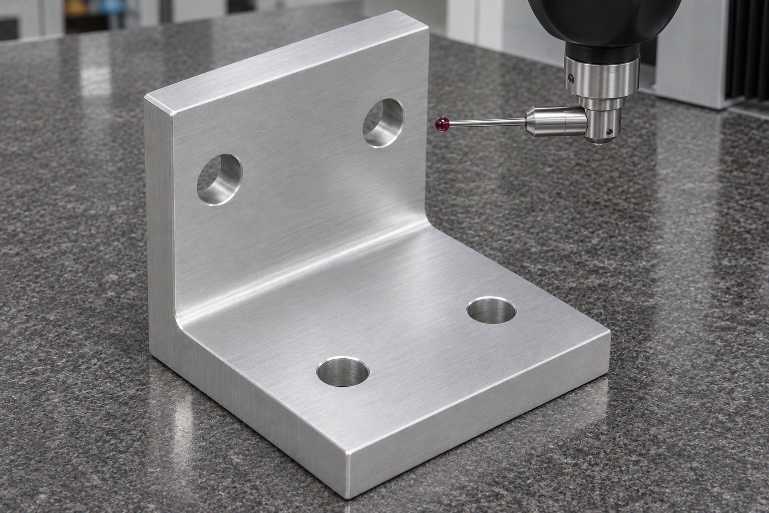
Prepare a feature-based first-article report
The proposed report would document the drawing revision, material record, supporting condition and datum setup. Foot form, upright orientation and both hole patterns would be checked using suitable instruments and accessible measurement paths. Fillets and edge breaks would not unintentionally define reference planes. Results would come from actual components rather than programmed coordinates or a visual square check alone. This example contains no fabricated numerical readings or acceptance rate. Any actual deviation would require documented disposition and reinspection where appropriate. The report should be clear enough for the buyer to understand which geometry was measured and under what condition.
Observe an unloaded dummy installation
An inert envelope could be assembled against an identified bench base with the specified hardware. The trial would record revisions, contact sequence and any interference at the root or mounting pattern. It would remain non-operating and would not use a live heater to justify component conformance. If fastening changes seating, the investigation would include base geometry and screw behavior. A successful fit would not establish temperature regulation, safe installation, clinical suitability or equipment load capacity. Those matters belong to separate qualification. A conforming bracket would not be altered merely to match an uncontrolled dummy or a fixture built to a different revision.
Control deviations and repeat-order decisions
A confirmed rocking condition would prompt review of the foot, burrs and fixture support. A local mounting conflict would prompt checks of the appropriate pattern before material is removed. Rework would require authorization and inspection of affected features. Repeat orders would reconfirm alloy, drawing, mating envelopes, finish and acceptance conditions before old tool offsets are reused. Tooling or fixture changes would be reviewed for their likely effect on the related planes. The quotation would distinguish bracket machining, first-article reporting and development of any special dummy fixture. Mechanical component release would remain separate from approval of an operating gel warmer installation.
Dispatch without bending the angle
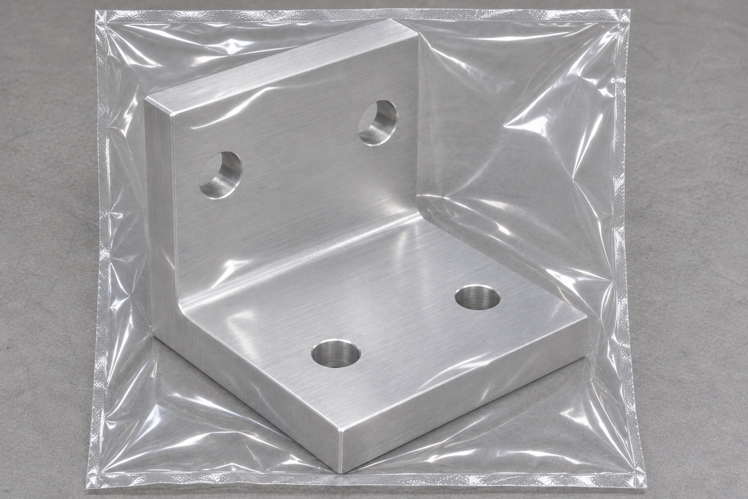
Packaging would support the bracket so the foot and upright cannot be bent by straps, stacking pressure or loose components. Defined contact faces would be protected from scratching and packaging debris. Hardware and dummy references would be separated from the machined part. Protective materials would follow the order's handling condition without sterile claims. Revision, material and inspection records would remain linked to the packed bracket. A final visual check would cover corner damage, retained chips and hole exits. This representative route explains a proposed aluminum fixture-part manufacturing plan without asserting an actual shipment or validated thermal, electrical or clinical performance.
FAQ
Is this a real delivered gel warmer accessory?
No. It is a representative machining proposal for a non-operating service fixture. No delivery, certification, thermal result or mounting approval is claimed.
What features are included in the angle?
A rectangular foot and upright, with two plain through holes in each plane, define the example. Threads, slots and electrical features are not included.
Why distinguish the foot and upright hole patterns?
They have different directions and interface roles. Separate definition and inspection prevent an ambiguous flat layout from concealing an alignment error.
Can a visual square check replace the report?
Not automatically. The drawing determines the geometric requirements and suitable methods. Record actual results using the approved references and support condition.
What if coating is added later?
Review its effect on seating and holes, define masking where required and inspect the accepted final condition. Do not assume every coating change is cosmetic.
Does a successful dummy installation validate the warmer?
No. It only records limited mechanical fit. Temperature control, electrical safety, loading and clinical installation approval require separate responsible evaluation and evidence.

tanghangyun@oemach.com