
Define the example and its boundaries
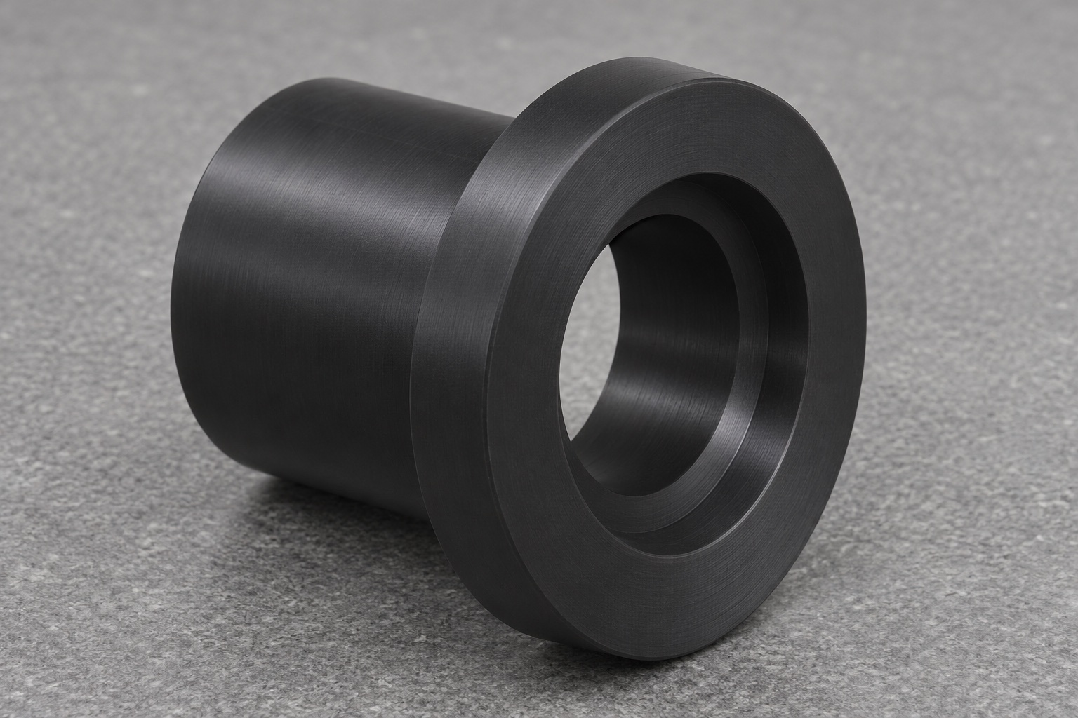
This representative case describes a black PEEK sleeve for a dental curing light engineering bench. It locates a dummy adapter relative to a carrier and surrounds a defined opening. A flange seats against the carrier, a smaller outer pilot enters its seat and a stepped through bore clears a tip surrogate. The plan describes custom CNC turning, dimensional inspection and a mechanical fit check with the source off. It does not represent a customer delivery, optical test result or clinical qualification. The sleeve is not a protective filter, and no claimed light attenuation or patient use is part of the scope.

Collect the inputs that determine fit
Obtain the controlled drawing, carrier dimensions, adapter envelope and relevant machining and inspection notes. Define the flange contact face, the pilot's usable length and the larger and smaller sections of the bore. Mark the permitted edge breaks and location of the internal step from the drawing reference. Identify maximum dummy tip size and any protected surfaces. If the customer expects a finish for a specific optical reason, record that finish separately and identify who evaluates it. A standalone CAD model often shows shape but omits which surfaces govern acceptance and how to support the sleeve during measurement.
Prepare the polymer blank
Start with the specified black PEEK rod form and documented grade. Label the lot and keep unused material identifiable for reorders. Select a blank diameter that gives secure support without extra material that can increase the number of roughing passes. Review the thin wall at the aperture and choose a grip that avoids directly squeezing it. If the drawing calls for conditioning or a particular stock treatment, confirm that before cutting rather than assuming it applies to all polymer forms. Track stock and finished pieces separately. Pilot pieces with unknown incoming history cannot provide a reliable comparison of machining routes.
Turn the working faces and external pilot
Face the accessible end and create the outside locating diameter while support is available. Leave enough stock for rough boring without making the final wall unstable. Where geometry permits, combine finishing of the outer pilot and the functional bore references in one setup. Use short tools with access to the step, keep chips from dragging over the flange and inspect the grip zone before committing to the pilot. Verify that the locating surface starts and ends where the fixture actually engages it. If the second face requires reversal, use a supported setup that protects the finished pilot.
Rough and finish the two-step bore
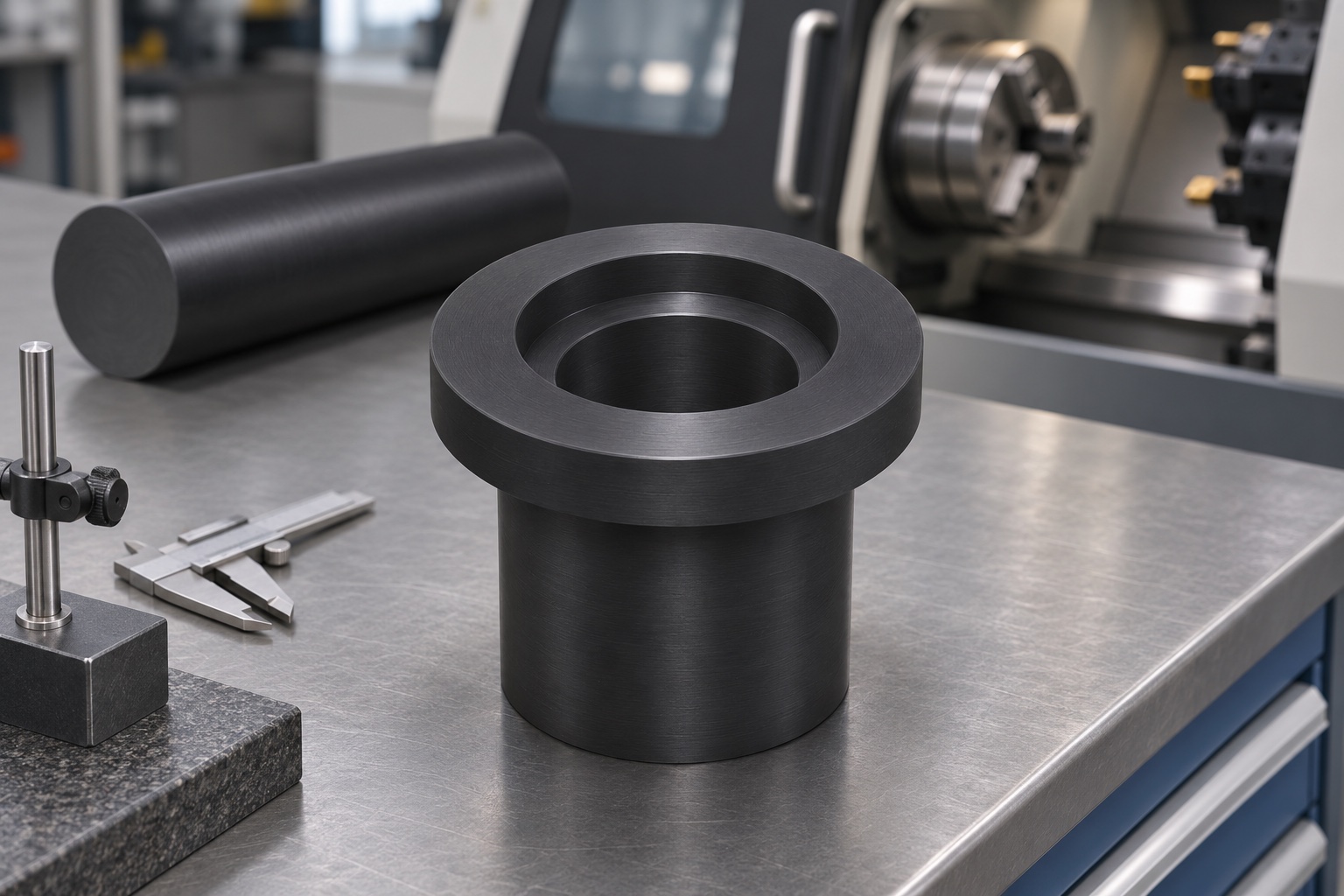
Rough from the open end with allowance for the final contour and shoulder position. Finish the small through section and the larger counterbore from the same axis when tool reach and stability allow. Clean out strands before taking a final pass. Avoid pausing where rubbing can leave an irregular band at the step. Establish the shoulder depth from the specified face and maintain clearance for the tool at the transition. On a trial part, check shape after release to see whether thin-wall deformation remains. If a correction is needed, verify the setup and tool load before trying a different diameter offset.
Deburr and inspect both ends of the opening
Remove loose fibers or turned edges from the entrance, the small bore exit and the interface between the steps. Keep the usable aperture and flange seating face intact. Inspect with appropriate light and magnification for an edge that has rolled inward. Do not enlarge the opening by hand to clear a trial pin. If an appearance requirement applies, distinguish it from roughness, geometric tolerance and optical performance. Clean by the approved method and protect the flange from abrasive trays. Keep the handling condition recorded with the parts. No particular chemical resistance or sterilization route is assumed in the example.
Let the released sleeve stabilize
Place the first piece on a clean support and wait until the agreed measuring condition is reached. Check bore and pilot in the required directions and depths. Compare readings across repeated placement without using unnecessary probe pressure. If diameter appears different when rotated, examine ovality and fixture influence separately. If a dimensional change occurs only as the part cools, record the trend rather than compensating blindly. A machining change should be tested on another sample under comparable conditions. Keep useful inspection data tied to actual part IDs; an estimated nominal value is not a measurement or evidence of manufacturing capability.
Measure position and shoulder depth
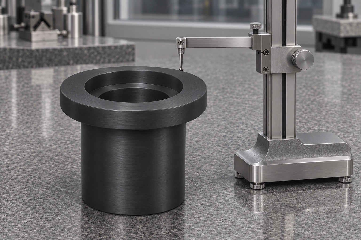
Use the flange seat and pilot to establish the drawing datum arrangement. Measure both bore centers with a method that reaches beyond the lead-ins. Check the axial location of the internal shoulder with an appropriate calibrated instrument. Do not use a broad probe where it bridges the step radius or touches the wrong feature. Record the relevant sizes, axes, depth and reference condition. If the requirement concerns a clear aperture at assembly, define a supplementary gauge or inspection setup rather than treating a plug alone as proof. Protect the bore from contamination or abrasion while changing setups.
Check fit with a de-energized fixture
Mount the sleeve on a non-operating bench carrier under the agreed restraint. Verify full contact at the flange and correct depth, then insert the permitted dummy tip by hand without force. Check the opening, clearance to the shoulder and ease of removal. If the dummy touches only after tightening, look at mounting force and the reference seat before recutting the sleeve. Record the carrier, surrogate and assembly revision. The check addresses mechanical location and removal only. It does not measure irradiance, stray light or optical protection. Any powered test belongs to a separate procedure validated by the equipment owner.
Respond to pilot deviations without guessing
If both diameters pass but the path is obstructed, inspect relative axis position and shoulder edges. If the flange stands off the carrier, check the corner relationship and burrs on both mating parts. If geometry appears correct before a later finish but not afterward, verify the part condition and accepted process before editing CNC offsets. Document the symptoms, confirmed cause and corrective action. Consider a two-setup route only if the datum transfer can be demonstrated with the required inspection. Repeat the critical measurement after the change and obtain approval before revising the drawing or accepted finish.
Agree on deliverables and reorder controls
Specify material identification, revision and first-article report with the quote. If a fit trial is part of the purchase, define the fixture, dummy and evidence required. Clarify whether the proposed price includes setup development, finishing and protection. Retain the released stock and measurement condition so repeat orders are compared on the same basis. Require a new initial check after an approved change to gripping, material or critical tools where appropriate. Establish how any discrepancy will be escalated before further lots are run. This case proposes controls and does not report a customer outcome, production rate or acceptance statistic.
Protect the sleeve in transit
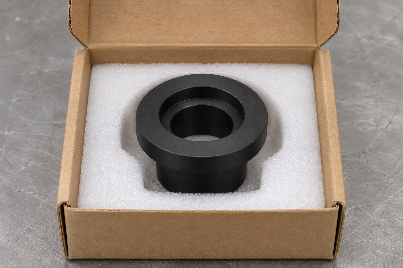
Use a clean compartment with distributed support under the body and clearance around the flange and bore. Do not press a shipping protector into the opening unless approved for the geometry. Avoid narrow bands that can load the wall and keep loose hardware separate. Match the package label to the material lot and drawing revision. Keep the report accessible without placing it against the working surfaces. The package is physical protection, not a sterile barrier. At receipt, check the aperture and flange for marks and measure in the agreed state if any damage or distortion is suspected.
FAQ
Is this a documented curing light customer project?
No. It describes a representative route for manufacturing a development fixture sleeve, without a shipment, certification or measured optical result.
Can the two bore steps be inspected with one plug?
A single plug does not measure each diameter, its center or shoulder depth. Use the stated inspection methods for each critical feature.
What should be checked after unloading from soft jaws?
Check the accepted diameters, shape and face relationship in the released condition. Compare results only after agreed stabilization.
Why keep the opening edges separate in the inspection plan?
The working opening and handling edges have different functions. An uncontrolled edge break can change the contact or clear aperture.
Does the fit trial establish light attenuation?
No. Source, detector and measurement conditions must be evaluated separately. A mechanical fit is not evidence of optical performance or safety.
Can a different black polymer be substituted?
Only with approval. Verify the specified material form, machining behavior and any separately defined functional requirements before substituting it.

tanghangyun@oemach.com