
Set the scope of the manufacturing example
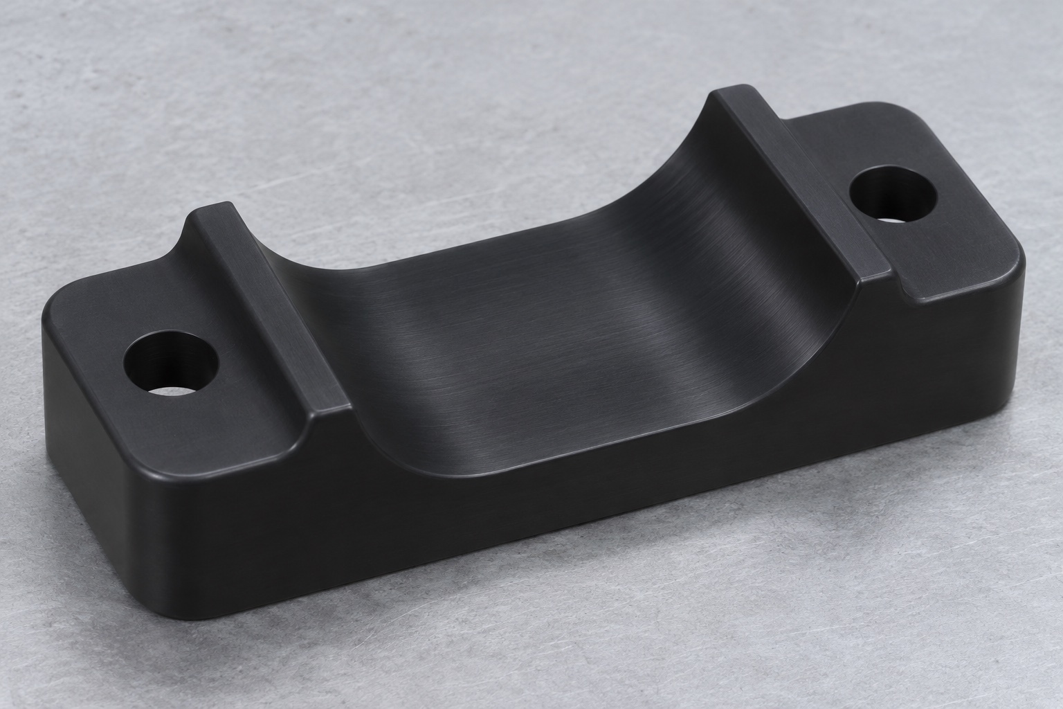
This representative machining case concerns a black POM-C saddle for supporting the body of a closed dummy tube in a hematology analyzer mixer fixture. It has an open concave channel and two mounting wings with through holes. The saddle attaches to a carrier, and the retainer is a separate assembly item. The example proposes a three-axis CNC milling route, dimensional checks and an optional bench fit. It does not document a customer delivery, regulated equipment approval or any clinical or mixing result. The approved drawing and complete assembly requirements would govern final manufacturing and acceptance.

Define the contact and mounting interfaces
Request the tube dimensional envelope and show where the cradle can touch the body. Identify the area where the cap and any permitted label must remain clear. Mark the required section of the arc and the intended height from the underside. Show how the wings attach and how the part locates if the screw holes have clearance. Record the carrier and retainer interfaces separately from the saddle drawing. Confirm whether a measuring master is supplied and what its diameter represents. A complete drawing package lets the shop distinguish a meaningful height check from a fit impression using one convenient sample.
Cut and identify the blank
Select black POM-C in the approved stock form. Identify the lot on the traveler and set a repeatable stock orientation for pilot pieces. Saw enough extra material for a stable grip without making the part unnecessarily thick. Check the blank for surface damage and bow before machining. If the buyer specifies conditioning, record its timing and required final measurement state. Do not replace the specified grade with unidentified offcuts just because both appear black. Retain a record of the stock and roughing sequence so any later shift can be investigated without guessing which material condition was used.
Establish the support face before roughing
Create the base face and suitable side references while the blank is still stiff. Use a broad support with clean contact points and a clamp load that does not distort the wings. Confirm the cutters and clamps clear the open channel. Rough the profile while the part still has sufficient section and leave a consistent finish allowance. If one-sided stock removal causes movement, compare a balanced roughing route in the pilot. Remove chips so they do not pack under the fixture or recut into the contact area. Recheck the seating face after release before treating it as a reliable inspection datum.
Machine the holes and contact arc
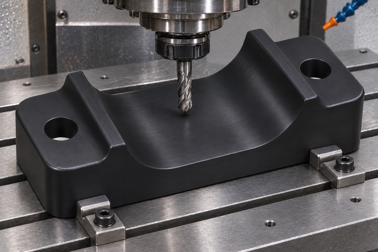
Position the two mounting holes from the agreed datums. Rough the channel and generate the contact arc with a tool and step-over selected for the finish requirement. Keep the cutter entry and exit away from the working contact band when possible. Do not treat the programmed radius as the finished part measurement. Inspect an early piece for a center ridge and check both open ends for tool marks. If the final arc requires a separate pass, preserve the same locating references. Complete the outer contour with support under the base so the wings do not flex as the cutter approaches the mounting holes.
Finish contact edges and clear the holes
Remove loose material at the channel lips and hole exits. Use the specified edge break and avoid broad hand rounding that changes where the tube rests. Check the bottom face for raised burrs around the mounting holes. A burr under a wing can tilt the whole part even when the arc was machined correctly. Use suitable light and magnification to inspect the black surface. Clean with the agreed method and keep the accepted pieces away from abrasive pads and swarf. No particular chemical resistance, cleanliness class or sterilization method is part of the proposed route unless separately specified and verified.
Let the pilot part reach its inspection condition
Place the released part on the defined inspection support and let it reach the required temperature or conditioning state. Confirm that it rests naturally and does not rock on a chip or pressure mark. Where the drawing requires restrained inspection, record the support positions and fastening condition. A tactile check should not use enough force to move the channel or lift a wing. Compare repeat readings on an early piece to identify whether the measurement process itself adds variation. Do not apply a machining offset in response to one unstable reading. Keep the measured condition with the first-article record.
Report the critical profile and mounting dimensions
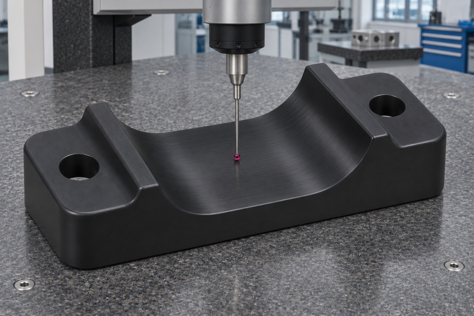
Measure the arc at the agreed stations and relate it to the seating datum. Use a suitable optical view for the accessible ends and an approved method for inner stations if specified. Inspect the mounting-hole pattern, base contact and relevant overall geometry. A clean master tube can check its seated height from the base. Document the gauge diameter and the condition of the part and fixture. If the master marks contact at only one high point, confirm the arc before accepting the height. Report actual pilot readings only when measured; this example provides no dimensional or process capability result.
Assemble the cradle on a representative carrier
Use a non-operational bench carrier and specified screws, then insert empty dummy tubes that represent agreed boundary conditions. Verify seating, cap access and clearance to the separate retainer. If the approved fixture checks motion, observe whether the tube envelope contacts adjacent hardware during that limited check. Do not change the clinical device or use patient material. Record the carrier, retainer, tube and mounting condition. If a part seats correctly before mounting and not afterward, inspect the contact surfaces and torque condition before reworking the arc. The test does not validate mixing, retention life, specimen handling or device safety.
Resolve deviations in a repeatable order
If arc size seems correct but seat height is wrong, verify arc position and the reference plane. If end profiles match but a master rocks, examine the channel for a central ridge or bowed base. If a cap interferes only on one tube variant, check the stated envelope and fixture position before removing material. Document any requested change against the drawing and repeat the relevant measurement after approval. Retain the pilot setup, material lot and gauge method when moving to repeat production. An approved sample is useful as a reference but does not replace the dimensional plan for the next lot.
Make the quotation and records unambiguous
Quote machined parts, a dedicated holding fixture and inspection development separately. State whether the buyer supplies the carrier, dummy tubes and fasteners. Request a material identification record and a dimensional report tied to the drawing and part lot. If an optical trace or seat-height gauge check is required, describe the section, fixture and accepted measurement state. Clarify the treatment of visual marks and protective packaging in the purchase order. A low-volume CNC machining quote can then be evaluated on the same scope as a competing route, rather than comparing a component-only price with one that includes fit verification.
Pack on the base, not the channel
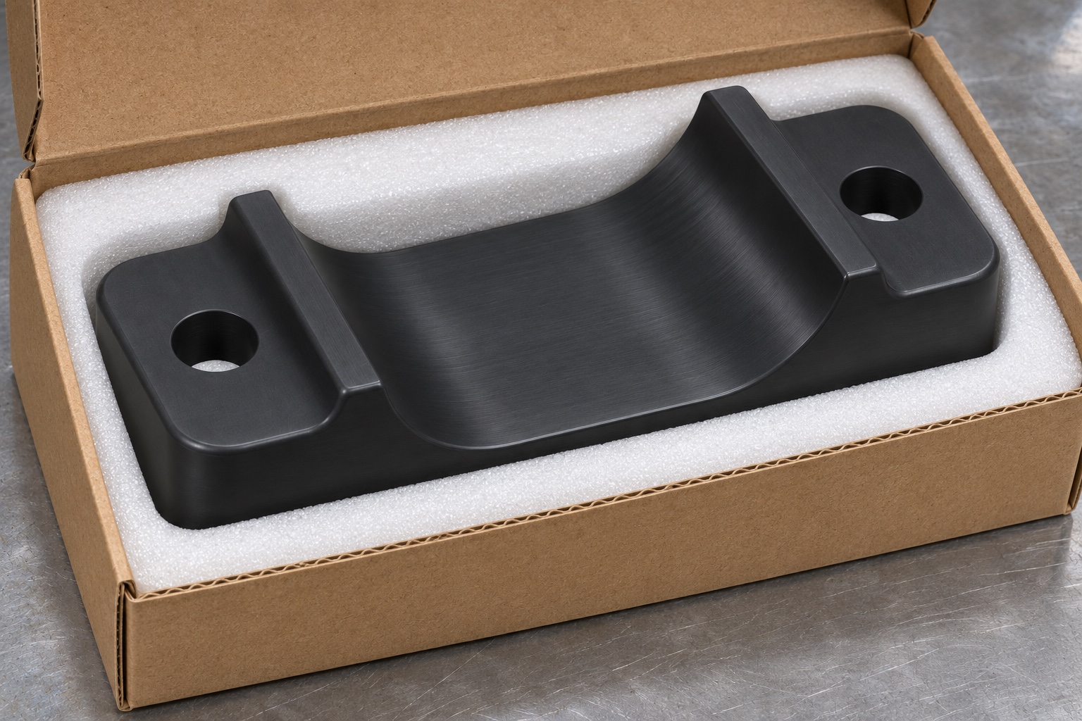
Use one dedicated recess per saddle, with flat support under the base and no pressure at the curved contact area. Keep screws and reference parts separated so they cannot rub the channel. Identify the part lot, material and revision on the outer package or traveler and keep the inspection record connected to those identifiers. This is ordinary protection during transport, not sterile packaging. At receiving, inspect the channel and screw exits and clear away any packing debris. Repeat the height check if there is evidence of impact, shift or local loading before using the saddle in the fixture.
FAQ
Is this an actual analyzer delivery?
No. It is a representative component machining and inspection route. It does not identify a customer or report device certification or test results.
Why keep the mounting holes separate from tube location?
They secure the saddle to a carrier. The arc and defined datums establish where the tube sits, and ordinary clearance holes may not precisely locate the saddle.
What should the first-article report cover?
Use the drawing to define required dimensions. Useful items include arc profile at stated stations, mounted references and seat height under the agreed condition.
Can the tube cap rest on the arc?
Only if the design expressly calls for it. In this example the body is supported and the cap stays clear.
Why check both the part and a master tube?
Direct measurements identify geometry, while a master can help reveal local contact and seating issues in a defined fit condition. The two checks serve different purposes.
Does this case recommend a clinical mixing procedure?
No. It covers mechanical manufacturing and bench fit with dummy parts. Clinical operation and device validation are outside the scope.

tanghangyun@oemach.com