
Scope of the proposed component
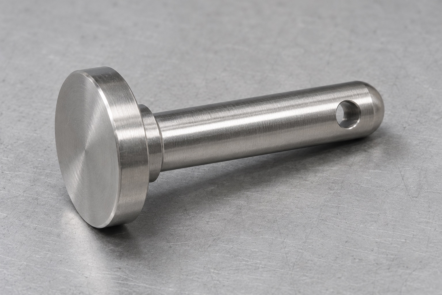
This representative machining case describes a 316L stainless steel cross-drilled handle pin for an ultrasonic instrument-cleaning basket. It has a turned head, a working shank and one transverse hole near the far end. The head sets the insertion stop and a separately specified clip provides retention. The work discussed is custom CNC machining to drawing and inspection on an unloaded fixture. It does not describe a customer delivery, a certified basket or any measured load or cleaning result. Before release, the equipment owner would define the mating stack, allowable clearance and approved retention hardware.

Read the drawing against the assembly
Mark the face under the head that actually contacts the basket tab. Locate the cross-hole from this face rather than the top of the head. Request limits for the shank, hole size and axial retention position. Check whether the shoulder blends into the shank with a radius that could prevent full seating on a square-edged tab. Document the intended clip insertion side and any obstruction from neighboring wires or washers. If the drawing only gives overall length and the hole is dimensioned from the tip, ask whether the resulting tolerance stack protects clip access across all permitted assemblies.
Prepare the turning blank
Select traceable 316L bar in the specified form and record the lot on the work traveler. The head diameter drives the initial stock size; avoid unnecessary stock that increases roughing or limits tool access. Define a grip zone that will not damage the finished working surface. Confirm that the chosen machine and workholding support the exposed length. Keep the finished pin separate from blanks once dimensions have been accepted. For a small pilot, record the turning setup, measuring instruments and tool condition so changes made during cross-drilling can be assessed against a known baseline.
Turn the seating features together
Face the blank and establish the reference for the head and shank. Rough the shank and finish the bearing diameter and seating face in one setup if the tool reaches them cleanly. Form the specified shoulder relief without cutting into the useful running length. Check for dragged chips and surface marks before parting. If a second operation finishes the tip, support the pin with suitable soft workholding and leave the fit surface intact. Confirm the mating tab can seat against the designed face. A cosmetically clean head is not a substitute for a shoulder that seats correctly.
Transfer to a shoulder-stop fixture
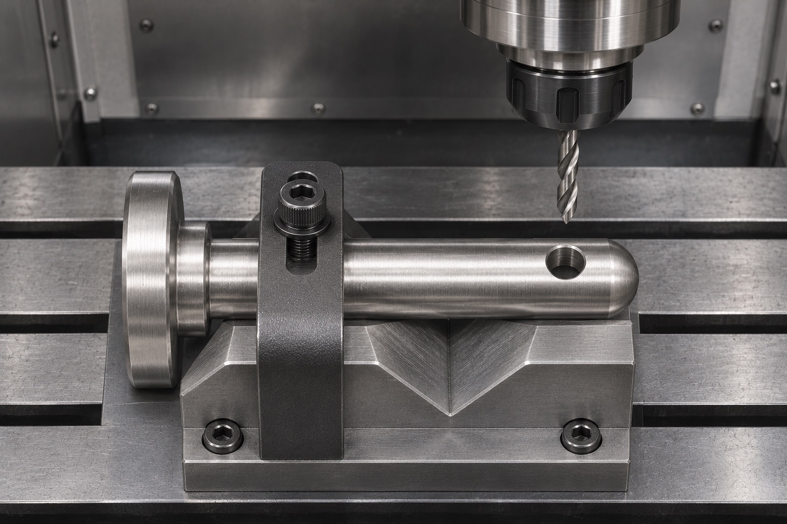
Locate the turned shank in a V-block with an end stop that contacts the working shoulder. Hold the pin down near the supported region and keep the clamp clear of the drill path. Provide a relief below the hole so the drill can break through without hitting the fixture. Verify the stop is clean at each setup change. Use a spotting method when needed to control entry on the curved surface. Check the first pilot hole at both openings. If its measured center shifts, investigate seating, tool runout and breakout before changing the program offset.
Control the transverse hole edge
Finish the hole to the drawing and remove burrs at both intersections with the shank. A fixed edge treatment is preferable to an uncontrolled chamfer where clip engagement depends on the hole edge. Inspect the exit under magnification and clean any lodged chips. Verify the tip and shoulder separately; a correct cross-hole does not excuse a sharp handling edge or a dent on the seating face. If a surface treatment is required, define when it occurs and verify the final state. No surface treatment, corrosion rating or equipment qualification is implied by the alloy choice in this case.
Choose gauges by feature
Use an appropriate outside instrument to check the working diameter at the specified positions. Use a plug or similar method for transverse hole size where suitable. To verify the axial relationship, seat the shoulder in the inspection fixture and locate the cross-hole relative to that face by a calibrated method. Do not let a loose gauge pin tilt and create an apparent location error. Measure the same feature from the same datum on the first and last pilot parts. Record instrument identification and note whether the finish was applied before the measurement. Report deviations against the released drawing only.
Compare a clip check with dimensional results
Install a clean example clip of the correct revision on the unassembled pin and note whether it passes without excess force. A clip that passes can still be inaccessible once the basket stack is in place. Pair the clip check with the shoulder-to-hole measurement and document any clearance issue. If the clip catches only at the exit, inspect for a raised burr rather than opening the hole beyond size. If it cannot pass with correct edges, confirm clip size and orientation. The proposed check supplements the drawing inspection; it does not replace it or establish retention strength.
Assemble an unloaded test stack
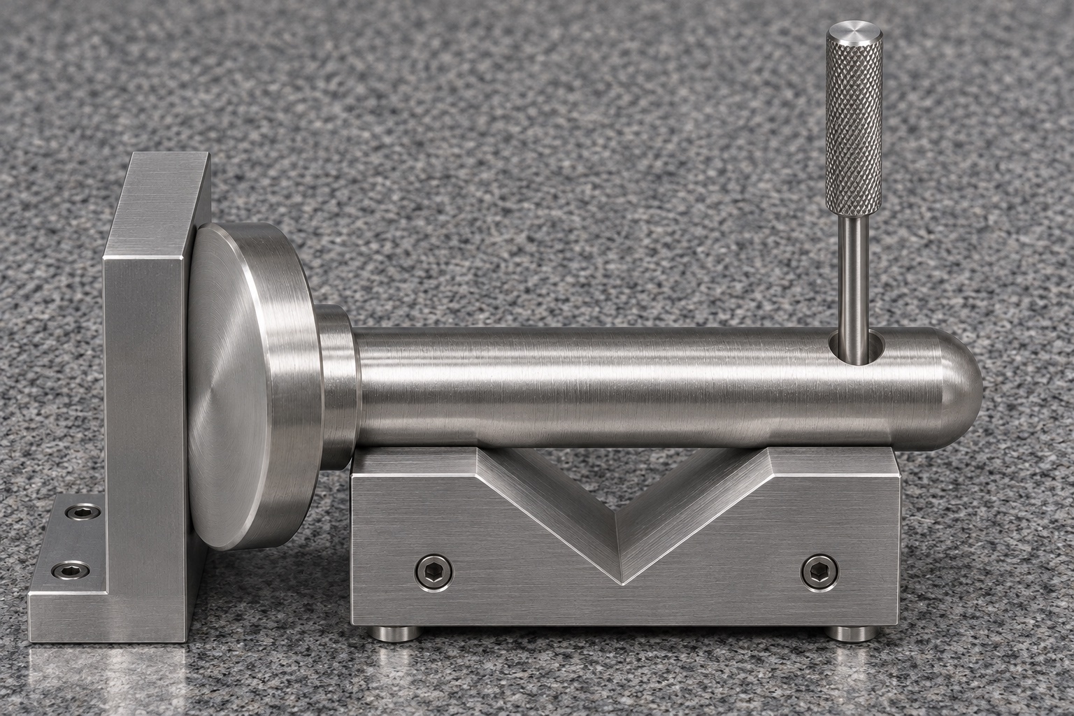
Use coupons or a non-operational basket fixture representing the allowed thickness and hole alignment. Seat the pin from the intended side, insert the clip and move the unloaded handle through its agreed range. Verify clearance at the head and clip. Record the limiting stack, the clip revision and the measurement method. If the head does not seat, check the shoulder radius and tab edge first. If end play is too large, re-evaluate the stack before changing pin length. No basket lifting, cycling endurance or instrument reprocessing conclusion is drawn from this fixture.
Decide what carries into repeat production
Retain the qualified turning and cross-drilling references, burr inspection method and setup records. A later switch to live tooling may be useful, but compare its finished hole position and edge condition with the agreed acceptance method. For low-volume machining, change only one variable at a time where practical so the cause of a shift can be traced. Recheck the first part after tool or workholding changes. Use sampling only as agreed; an isolated fit check cannot establish process capability. Control the clip separately so an unapproved hardware substitution does not change the inspection result.
Set the scope of the quotation
Ask suppliers to price the machined pin, any finish and first-article documentation separately. Provide the clip drawing and mating stack even if neither will be supplied with the pin. State whether the supplier must build a test fixture or use a buyer-provided coupon. Identify the dimensions and edge conditions to be reported and how part and lot identities should be carried. Clarify whether protective bags or divided trays are required. This makes a quote for a turned part with a drilled hole comparable to a quote that also includes proof of fit and documented edge inspection.
Prevent damage after final inspection
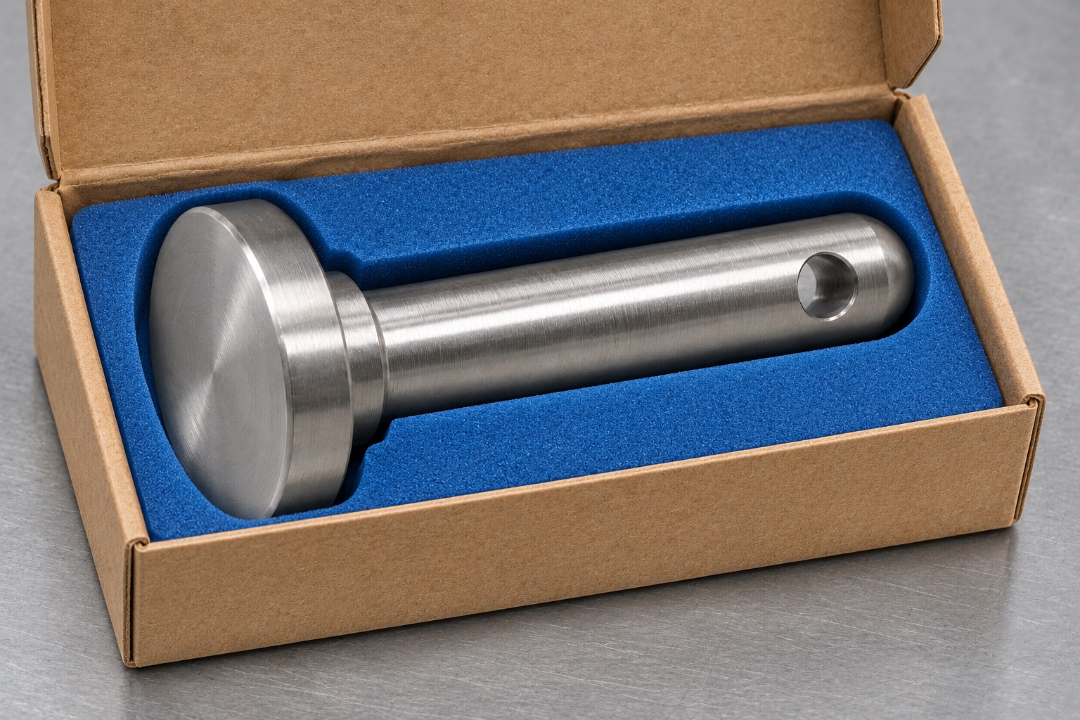
Place each pin in an individual slot with support along the shank and room around the head. Do not drop clips into the same slot unless the agreed package positively separates them. Protect the accepted running surface from pin-to-pin contact and keep the cross-hole clean. Label the carton or traveler with the drawing revision, material lot and quantity. Use the packaging only as protection during handling and transport. If a part arrives with a dent near the shoulder or hole, quarantine it for assessment rather than pushing it through the mating tabs.
FAQ
Is this a delivered customer project?
No. It is a representative CNC manufacturing route with proposed checks. It does not claim a customer, certification or measured performance.
Why use a V-block for drilling?
It locates the cylindrical shank while a shoulder stop controls the axial position. The fixture still needs stable support and clearance for drill breakout.
Which dimension controls access to the clip?
The shoulder-to-hole distance and actual tab stack govern axial access. Nearby structures and the direction of insertion also matter.
What if the clip fits before assembly but not afterward?
Check the stack thickness, full shoulder seating and access to the hole. Do not enlarge a compliant hole to compensate for an unrelated fit problem.
Can this route include passivation?
Yes, if specified and approved. Agree the procedure, traceability and the dimensions or surfaces to be checked after treatment.
How should loose clips be packed?
Keep them separated from the running surface and shoulder. Identify the clip revision and quantity if the order includes this hardware.

tanghangyun@oemach.com