
Set the scope of the example
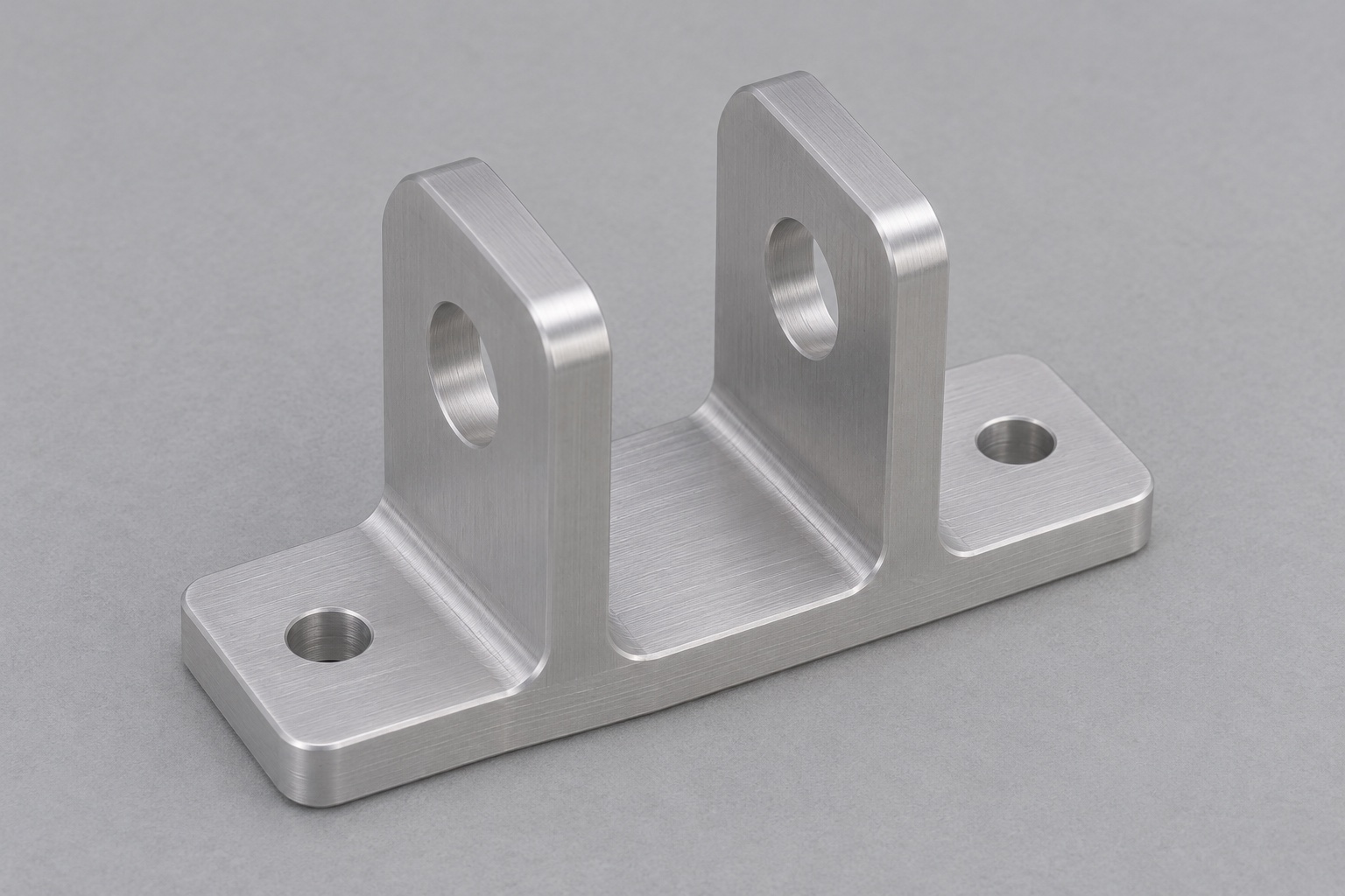
This representative CNC machining case describes a 6061 aluminum bracket for the ejector lever of a point-of-care diagnostic analyzer. A flat base bolts to an equipment chassis and two integral upright ears carry a common pin. The lever moves between the ears. This is an example of how to manufacture and inspect the component, not a report of a customer order or verified clinical equipment. No measurements or production outcomes are claimed. The working inputs would be a controlled drawing, a model and the pin and lever interfaces. Acceptance concerns the mechanical bracket and only those assembly interfaces agreed in advance.

Convert assembly intent into an inspection map
Use the underside as the main seating reference. Add a side and end reference if the assembly locates from those features; use a datum pattern instead if the drawing specifies one. Identify the two ear bores on the report as near and far relative to pin insertion. Record the intended relationship between both axes and the mounting plane. Separate those dimensions from ear gap, bolt-hole spacing and root fillets. The drawing should show the pin envelope and any spacer thickness that consumes clearance in the channel. The mounting screws should not be treated as close-fit locators unless the design actually requires that condition.
Choose stock and orientation
Select 6061 in the specified temper and stock form and keep the traceable lot with the traveler. Orient the blank so the base and ears can be milled with access to their roots. Saw enough material for workholding and for a clean seat, but avoid adding stock that requires an unnecessarily long cutter reach. Separate the acceptance surface from any temporary grip land that will be removed. Where the stock can move during heavy roughing, leave a finish allowance and check the base between operations. A sequence that leaves a bowed underside while making beautiful ears does not solve the actual seating problem.
Establish the base and rough the U channel
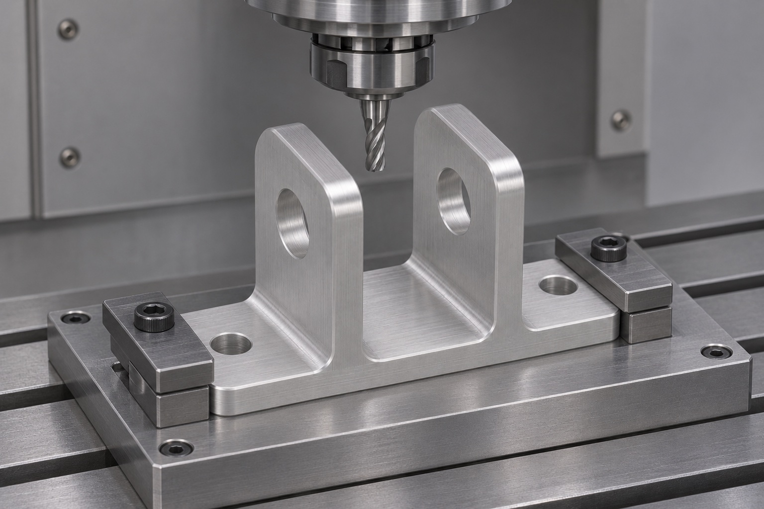
Face the main seating surface and create the transfer references for the next setup. Support the blank directly under the channel and cut the bulk material before completing the ears. Alternate where useful so one ear is not left thin while the opposite side still needs heavy cuts. Keep the root radius consistent with drawing and cutter access. For a short lot, a simple soft-jaw or base-supported fixture may be appropriate if it repeats and keeps chips off the seat. Verify the clamp load does not create temporary flatness that disappears when the bracket is released. Record the rough stock condition before finishing.
Finish mounting features and the inside gap
Use the working datum to finish the mounting tabs and holes. Inspect the seat free of clamp pressure. Finish the two channel faces with tool engagement that limits side loading, checking upper and lower gap so taper is visible. Leave only the specified chamfers on the channel edges. Verify that neither root fillet nor a protruding screw head interferes with the lever envelope. If the design allows, keep contact between the fixture and the base only. Thin ears should not be squeezed together to make the part easy to hold, since that can alter both gap and bore alignment once the clamp is opened.
Set up for the two lateral bores
Mount the base against a repeatable side fixture or use a validated reorientation to give the tool line of sight across both ears. Confirm that the spindle can reach the far bore without interference. Establish starting holes before final sizing, and check the far side on the first piece instead of extrapolating from the near side. If the pin has a retaining fit on one side, use the drawing-specific finishing tools and acceptance gauges. Where a through tool cannot reach safely, use separately aligned setups and include the datum transfer in the inspection plan. There is no automatic preference for a setup that cannot be measured.
Review edges and surface treatment
Remove burrs on all four bore edges and on the mounting holes. Check the inside faces visually and tactilely only where permitted by the inspection method; a folded burr can remain hidden in the bore shadow. If finish is specified, agree masking, electrical contact locations where relevant and post-finish acceptance. Do not count on an oversize hole to compensate for an unspecified coating change. Preserve the main seating surface from abrasive damage. Clean parts per the drawing and keep mixed finish conditions segregated with their travelers. The as-machined example does not imply any coating, corrosion rating or cleanroom classification.
Build a first-article inspection setup
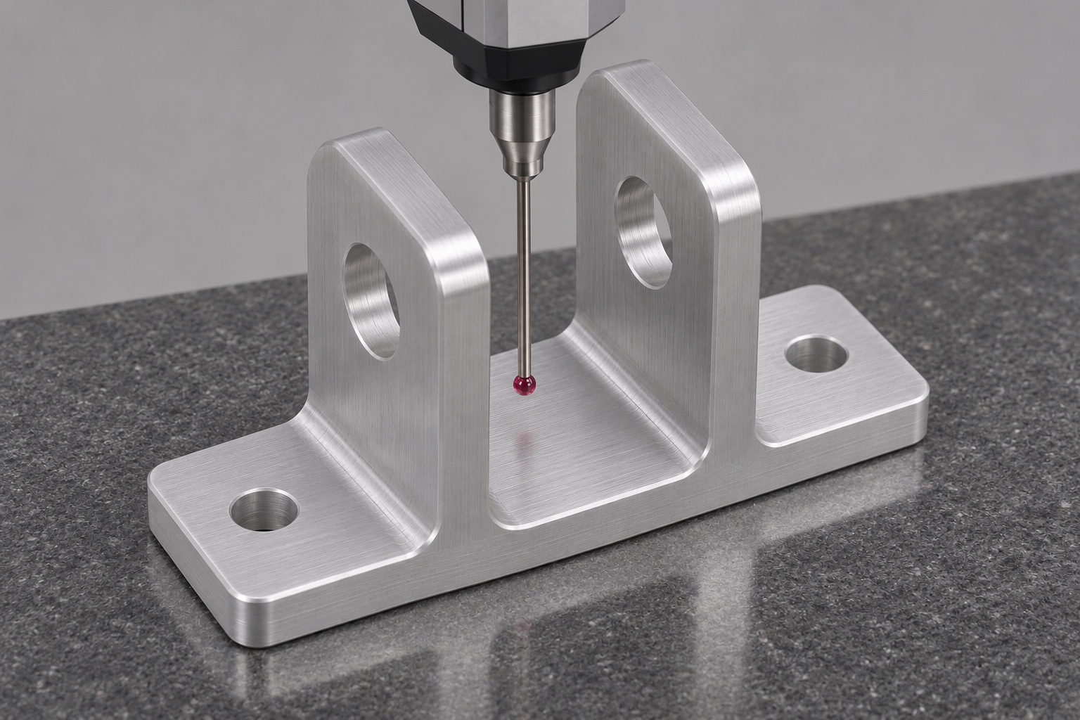
Place the base on a stable measured support and verify the coordinate system from the defined datums. Sample both bores, distinguish center position from fitted diameter and use suitable depths clear of chamfers. Measure the channel gap at the drawing locations and check the mounting hole pattern in the same datum system. Select an accessible stylus configuration and confirm it does not strike either upright ear. A gauge pin can supplement the measurement by checking passage through both holes. A report should note the state of the bracket and final finish. Example acceptance limits must come from the released drawing rather than an illustration.
Run an unloaded bench fit
Assemble the bracket on a representative chassis coupon with the specified mounting hardware and dummy lever. Install the nominal pin using the approved procedure and rotate the lever by hand within the defined envelope. Check pin retention access and the intended clearance to a non-functional cartridge surrogate. If the pin fits off the coupon but not installed, inspect mounting flatness, torque effects and seating debris first. If the lever scrapes but the pin passes, inspect the inner wall clearance and any spacer. This bench fit is proposed as an assembly screen. It is not evidence of diagnostic functionality or repeated ejection life.
Control the change from prototype to repeat lot
After the pilot, freeze the workholding orientation, datum sequence and tool used to finish the second bore. Keep the material and finish condition paired with the dimensional report. If a change is proposed, compare the new and prior setup on the axis relationship and ear gap rather than only comparing output dimensions measured at convenient points. A first piece after fixture maintenance or cutter replacement should repeat the defined checks. For repeat low-volume production, record how often the alignment and gap are verified. Only extend sampling when approved evidence and requirements support the change; no achieved capability is assumed in this example.
Request quotations with a common scope
Send suppliers the same controlled drawing and inspection requirements. List pin, lever and chassis coupon availability separately, since a component quote may not include a functional fixture. Specify whether the supplier should propose both an aligned-through operation and a two-setup alternative. Distinguish the cost of proving the first article from the repeat part price. Ask how the supplier intends to inspect the inner bore exits and verify alignment. Document responsibility for any anodizing and final size acceptance. This allows an engineering buyer to compare actual process choices instead of treating identical part descriptions as evidence of equivalent manufacturing scope.
Ship with support under the base
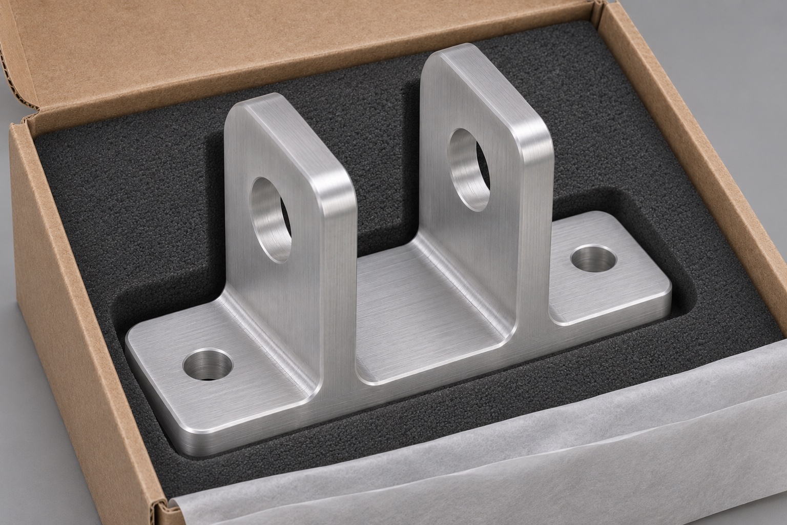
Use a fitted cavity that restrains the base and leaves room above and around both ears. A separator should protect the bolt tabs and seating face without pressing on the bore edges. If the job includes pins or screws, contain them independently so they cannot travel into the channel in transit. Label parts or packages as agreed and link the final inspection report to the lot. This is ordinary protective packaging for a mechanical component. At receiving, look for impact marks on either ear and inspect the base before using a master pin or the intended fixture to verify the installation.
FAQ
What makes this a representative case?
It specifies a proposed manufacturing and inspection route for an example bracket. It does not identify a customer, claim certification or report measured results.
Why inspect the bracket with little or no clamping?
Clamping can close the gap or flatten a bowed base. Record the intended measurement condition to avoid accepting geometry that only exists under fixture load.
What if the pin must press into only one ear?
Define both fits individually and check pin insertion and support in the intended direction. The retaining bore and the free bore do not need the same size.
What does the cartridge surrogate check?
It can show local mechanical interference during the defined bench fit. It does not evaluate specimen handling, reliability or the operation of a working analyzer.
Is a coating part of the case?
Not unless the released drawing specifies one. If treatment is required, clarify masked areas and verify the fit features in the final finish condition.
Which evidence should follow repeat lots?
Use the required dimensional report, traceable material and finish information, and the revision of the agreed fixture or mating components if a fit check is included.

tanghangyun@oemach.com