
Define the prototype as a mechanical setup part
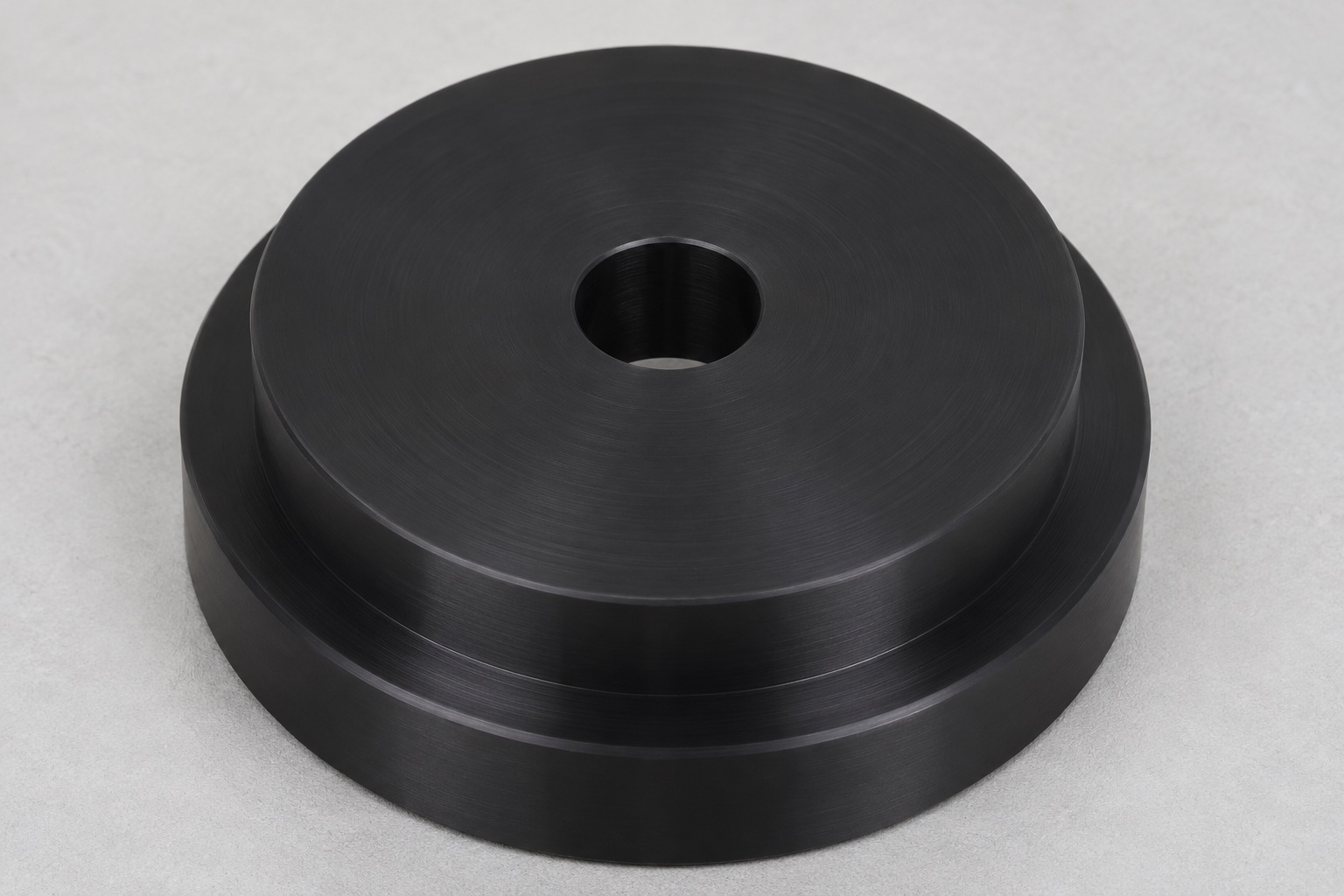
This representative case proposes a black POM-C puck for a dental laboratory scanner development fixture. The part is a stepped round disc with a central through bore and two working faces. An approved dummy model carrier sits on the top face, while the underside seats on a bench reference plane. A mating pin is the defined lateral reference. The order would cover the machined disc, agreed dimensional data and ordinary protective packaging. It does not describe an actual customer delivery, a commercial spare, a calibrated artifact or successful scanner performance.

Review the interface before quoting the disc
Obtain the current puck, pin and base drawings and identify the surfaces that should contact in the seated condition. Verify whether an external shoulder is needed for clearance or actually positions another part. Check the available pin length, shoulder radius and entry direction. If the bench trial uses a dummy carrier, confirm its seating face and how it is placed without adding an uncontrolled side load. Document the difference between mechanical fit and scanner setup. A drawing that gives only the nominal disc and hole diameters cannot define height, rocking or repeated seating acceptance.
Select and trace the stock
Use identified POM-C round stock of the specified black grade and condition. Record the lot before cutting blanks and keep the identity with the work in progress. Verify allowance for the bore, the larger diameter and both end faces. Inspect incoming material for damage where it could remain on a working surface. Confirm whether the order calls for a measurement temperature or stabilization period after machining. Do not replace the stock with a different dark polymer based on appearance. The drawing and material records establish what was ordered, not optical, biological or cleaning performance.
Establish the face and bore in the first setup
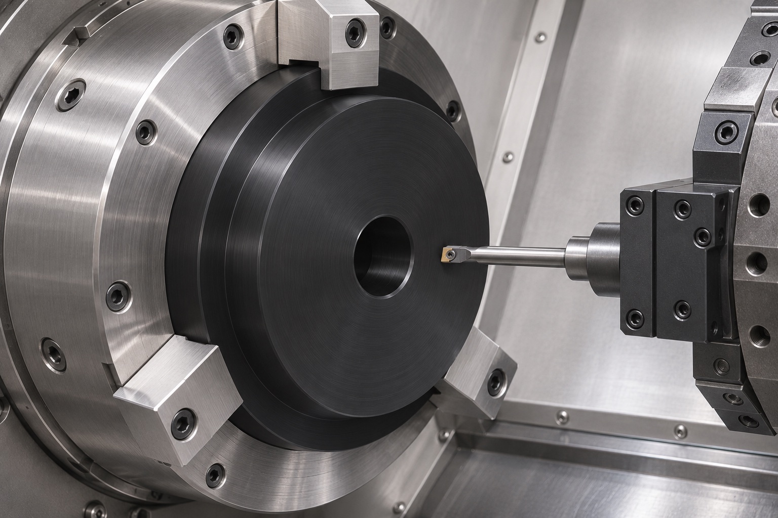
Face the exposed end, drill the through opening and finish it using a process suitable for the material and drawing. Turn the upper step and top face from the intended reference while access and support allow it. Keep clamping pressure controlled as the section changes. Leave sufficient material on the back for the second setup. Clear chips so the cutting edge does not drag them across the bore. Record what was measured in the primary setup and what remains to be checked after release. An acceptable in-process value is not a substitute for the final referenced result.
Finish the underside without distorting the bore
Reverse the disc using clean soft jaws on an approved outside surface. Use an axial stop on the designated face and confirm it seats without debris. Finish the underside to the specified height and create any required edge break on the bore exit. Do not use an expanding arbor in the bore without a validated workholding plan; expanding the polymer could change the geometry while it is being cut or marked. Check the released disc for rocking before changing the program. Record the setup so a second operator can reproduce the alignment between the base and top faces.
Inspect edge breaks and the usable locating land
Inspect the bore openings, step edges and contact faces under the agreed visual conditions. Keep the cylindrical locating land clear of slivers and the faces free of raised burrs. Remove only the edge material authorized by the drawing. If the entry radius prevents the disc from seating against the fixture plane, identify the actual interference before enlarging the bore. Avoid hand polishing the seating face to remove a cosmetic mark if it changes height or flatness. Reinspect working geometry after any approved edge correction and distinguish rejected or unfinished samples from the first-piece evidence.
Measure the released disc on defined supports
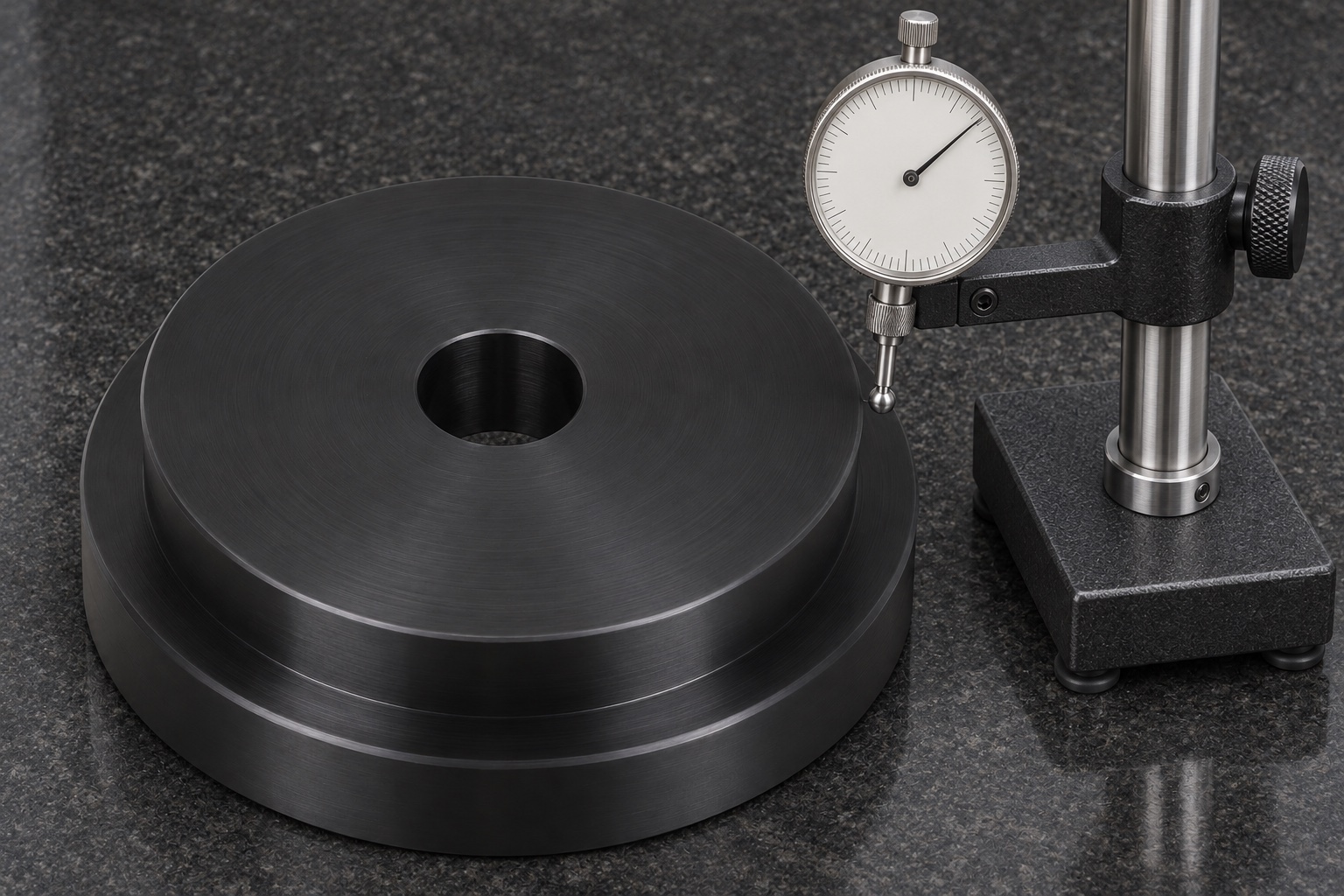
Verify bore size, outside step geometry and height at the drawing locations. Use an instrument with suitable contact force for the polymer, and record the condition after unloading. If top-face orientation to the bore is specified, establish the axis with an approved method and compare the relevant face. If the drawing calls for flatness, check it separately from overall thickness. Record actual values, fixture and measurement conditions and the revision. Where a single reading is affected by setup variation, repeat the seating and resolve the method before using the number to accept a part.
Run a limited reseating trial
Use a clean reference plane, specified pin and inert carrier, with revisions recorded. Seat the puck in the defined direction without abnormal force and observe any incomplete contact or rocking. Repeat the sequence as required by the agreed trial and record variation in the relevant mechanical measure. Stop if a burr, damaged fixture or wrong revision makes the comparison invalid. The trial covers only the chosen envelope and conditions. It does not prove scan accuracy or quantify a real scanner's repeatability. The equipment owner defines any device-level tests with approved parts, instruments and criteria.
Investigate the fixture as well as the part
If the puck binds at entry, inspect the pin tip, bore edge and entry radius. If it stops short of the plane, check the pin shoulder, debris and available engagement before reducing the disc height. If readings change with reseating, compare both the fixture and disc surfaces. Do not enlarge the hole merely to make an out-of-revision pin fit. Hold affected pieces and seek the approved disposition. A usable process record links the observed symptom to a correction and reinspection rather than declaring success after an unrecorded shop adjustment. Repeat-lot instructions should reflect only approved changes.
Define what moves from prototype to repeat order
Agree on the drawing revision, material evidence, measurement report, finish condition and any bench trial observations. Identify when a tool, stock or fixture change requires a renewed first-piece review. Check the current pin and support revision at the repeat order, because a mating change may alter fit even when the disc drawing remains the same. Quote any dedicated fixture, gauge or extra measurement separately. The proposed handoff does not include a scanner setup procedure, calibration report or claimed manufacturing capability. Record which open requirements must be resolved by the responsible equipment designer before production use.
Protect the seating faces in packaging
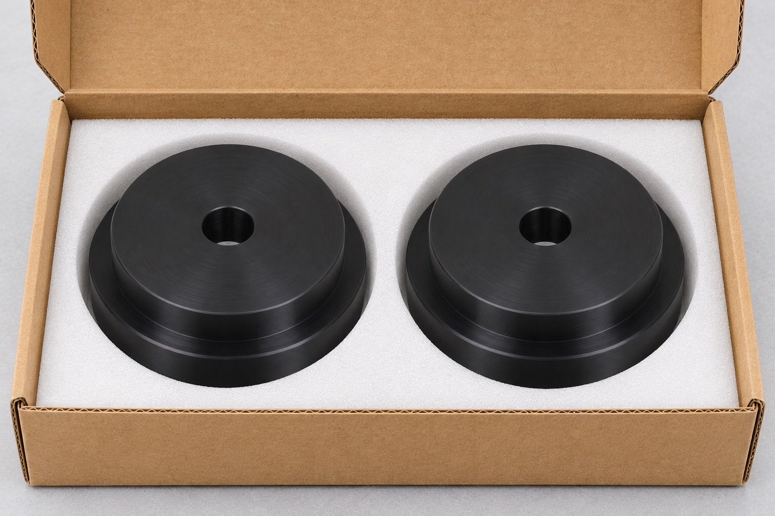
Use a divided tray or individual pockets that support the outside without putting pressure on the bore or rubbing a working face. Keep loose packing and adhesive away from the opening and flat seat. Identify the part, lot and drawing revision on the outside and tie them to the dimensional report. If a mating pin travels with the batch, keep it in a separate compartment. Ordinary protection is not sterile packaging. If a special receipt condition matters, define its handling and acceptance before release rather than assuming a sealed box establishes a controlled environment.
Keep acceptance tied to the drawing
The machining supplier can report actual dimensions and a limited mechanical trial if contracted. The equipment owner decides whether the part is suitable for the intended scanner development use and what further evaluation is necessary. Keep those responsibilities separate in the acceptance documentation, especially when the setup fixture and the disc are supplied by different parties. The example describes a possible manufacturing route and the evidence that would be requested, not a completed production lot. It does not report a customer, certified compatibility, calibrated optical response or a measured scanner result.
FAQ
What material does the example specify?
It proposes an identified black POM-C grade. The exact material specification, stock condition and traceability are determined by the actual order.
Why finish the underside in a second setup?
Reversing the disc gives access to the seating face. The transfer must preserve the specified relationship to the bore and top surface after release.
Can a go pin replace all measurements?
No. A fit check may show passage under a defined method, but it cannot establish face height, orientation or every bore characteristic.
What does the repeated fit check verify?
It documents mechanical seating in the specified fixture. It is not a scanner calibration or evidence of optical accuracy.
Is this compatible with a named scanner?
No such claim is made. This is a representative development part with hypothetical interfaces and no verified commercial compatibility.
What should accompany the prototype?
The approved drawing, stock identity, dimensional results, any limited trial notes and protected lot packaging. No results from a real customer order are implied.

tanghangyun@oemach.com