
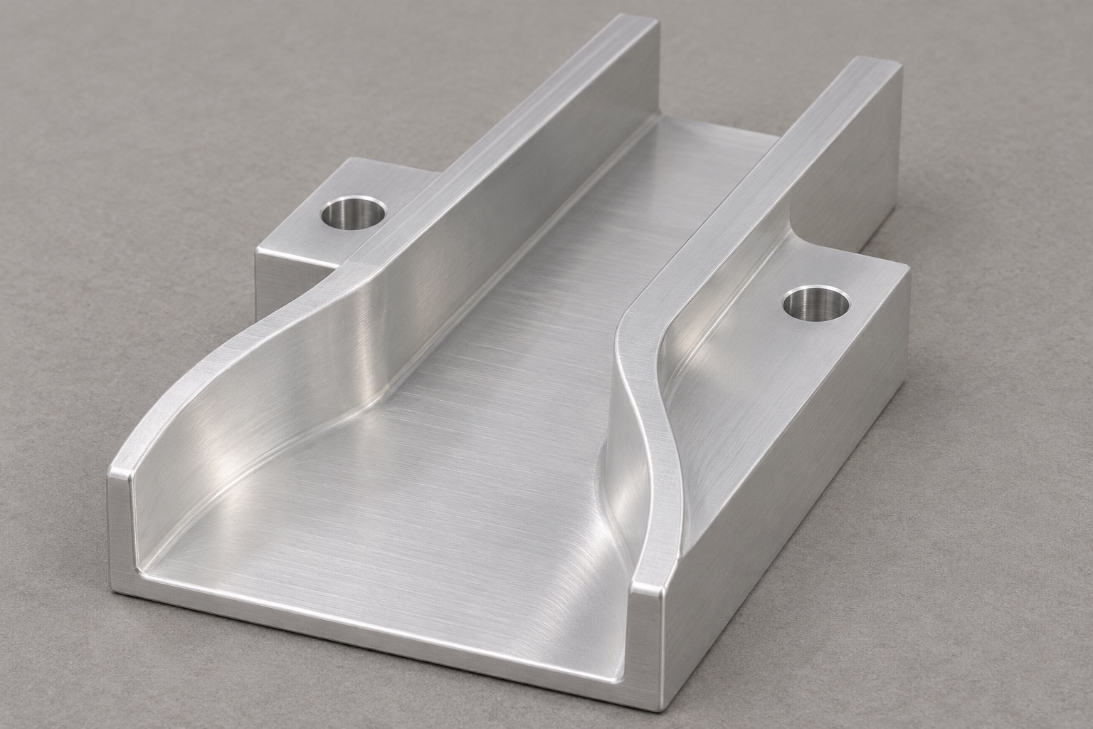
Propose a drawing-controlled transition block
This representative machining case concerns a 6061 aluminum cap-feed transition for a generic laboratory tube capper. It does not report a customer delivery, a compatible commercial spare or measured machine performance. The part has an open channel with a wide entrance blending into a straight narrow exit, a flat supporting floor and two flange mounting holes. It links two independently located guides. The proposed order covers manufacturing, dimensional verification, an optional limited bench trial and protective packaging. Cap sorting, torque control, sealing and instrument qualification are outside the component scope.

Review the three mechanical interfaces
Request the cap drawing, upstream guide exit and downstream guide entry. Check the direction of travel and mark the surfaces that support and constrain a correctly presented cap. At each joint, review the allowable height difference, horizontal gap and side offset. Identify whether the mounting base or another feature controls the final floor elevation. Confirm the screw and washer envelope before locating the flange holes. List any unresolved cap or guide revision as an open issue, not an implied fit. A nominal solid model is helpful, but dimensional limits and acceptance conditions must come from the released drawings.
Start with identified stock and a finish plan
Select 6061 stock of the specified condition and retain its lot identity with the blanks. Check the allowance under the planned channel floor and around the two flanges. Confirm which dimensions apply after finish if the order specifies surface treatment. Do not assume a particular coating build, appearance or cleaning resistance. Mark surfaces that must not be clamped or scratched. The traveler should state how the component is handled between milling, finishing and inspection. Material identification and an agreed finish record support component traceability, but neither establishes system-level material compatibility or a sterile condition.
Make the base and end references first
Face the underside and establish the side and end references used for the channel and mounting pattern. Support the blank along its base so it does not rock. Use clean stops and verify that a trial blank returns to the same position after reseating. Leave access for the channel cutter and for drill breakthrough near the flanges. Avoid relying on the rough stock width as an orientation reference. Document the locating scheme before roughing. If the base is refinished in a later setup, plan how the floor-to-base relationship will be recovered and checked in the final condition.
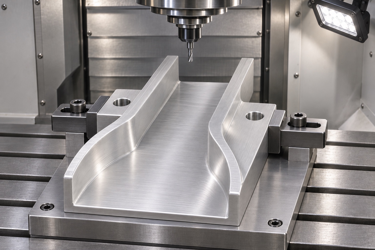
Rough and finish the flare and lane
Rough the open channel with enough allowance to finish the floor and the curved transition. Use a controlled finishing sequence that keeps the final floor elevation and both side profiles tied to the same references where possible. Support the flanges without pressing the finished walls inward. Inspect the first released part near the point where the flare meets the parallel lane, since a change in tool loading or an unblended toolpath can create a local step. Clear chips between passes. If the wall profile is wrong, check the tool and coordinate setup before making a correction that shifts the entire channel.
Drill and deburr the mounting holes
Drill the two flange clearance holes from the released references. Confirm the exits are clear and supported so burrs do not damage the seating plane. Check hole size, position and the fastener envelope independently of channel measurements. Deburr the underside without rounding the primary datum. At the ends of the channel, preserve the specified floor and wall shape while removing raised material. A larger edge break is not automatically better; it can change the contact at the guide join. Measure and record any drawing-controlled break or radius, especially after an operation that can alter it.
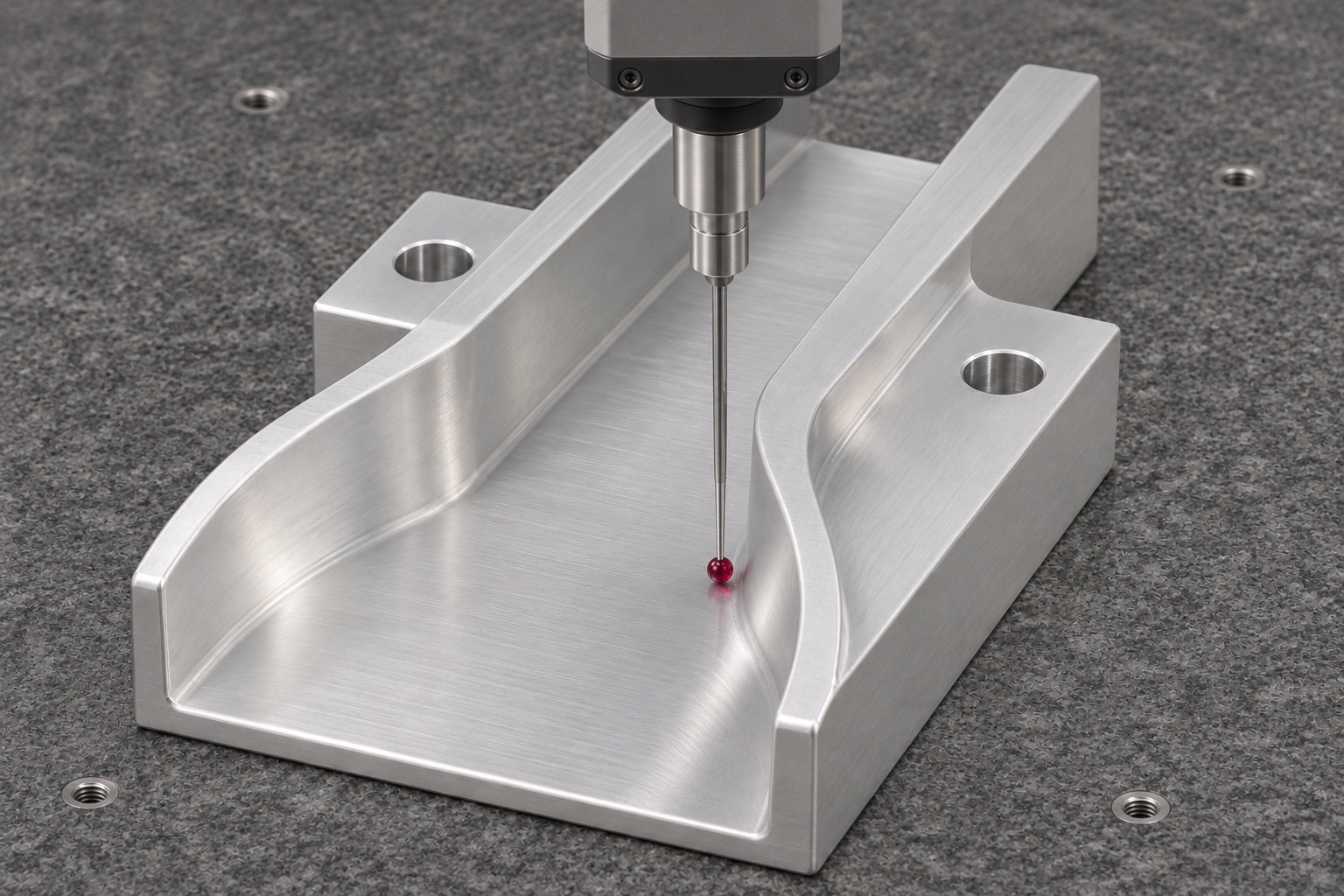
Verify floor elevation and wall profile
Set the part on the reference support and inspect the floor at the entrance, transition and exit. Compare each reading to the drawing's reference, not merely to the other readings. Check profile or width at agreed longitudinal positions and at the depth where the cap can contact a wall. Confirm clearance for the stylus in the corner areas, and avoid treating contact with a fillet as a floor reading. Record method, instrument, revision and actual data. If an inspection tool cannot resolve the required region, resolve that limitation with the drawing owner before deciding whether the part conforms.
Check the joint in a limited mechanical fixture
A bench fixture can represent both adjoining guides and the intended fastener condition. Confirm seating and measure the actual floor step at the joints. Pass a nonclinical cap surrogate or agreed sample through the assembly in the defined direction and observe where it touches. Use the approved trial force or motion, and do not force a cap across a snag. Record which cap and fixture revisions were used. A successful pass is evidence for that arrangement only. It does not establish production throughput, contamination control, closure torque or a sealed tube on the actual machine.
Find the source of interference before rework
If the cap moves through the isolated block but catches after installation, inspect both joint heights, lateral offsets and burrs at the base. If it binds inside the flare, compare the cap envelope and measured channel section before widening the entire lane. If the exit dimension moves when the bolts are tightened, examine support and flange seating rather than adjusting the tool offset immediately. Hold affected pieces until the disposition is approved. Record the corrective action and repeat the affected checks. A single successful manual pass after undocumented filing is not evidence that the drawing or repeat process is under control.
Define the records for repeat production
For the trial lot, agree on the drawing revision, material evidence, actual measurements, finish condition and any limited fit observation. Identify which changes to stock, workholding, tool or treatment require a renewed first-piece check. If a cap or adjacent guide is revised, revisit the assembled clearance even if the transition drawing remains unchanged. Quote the fixture, any special inspection and packaging separately from machining. This case describes a proposed manufacturing and acceptance route, not evidence of completed production. Keep the purpose of each record clear so a dimensional inspection is not mistaken for instrument validation.
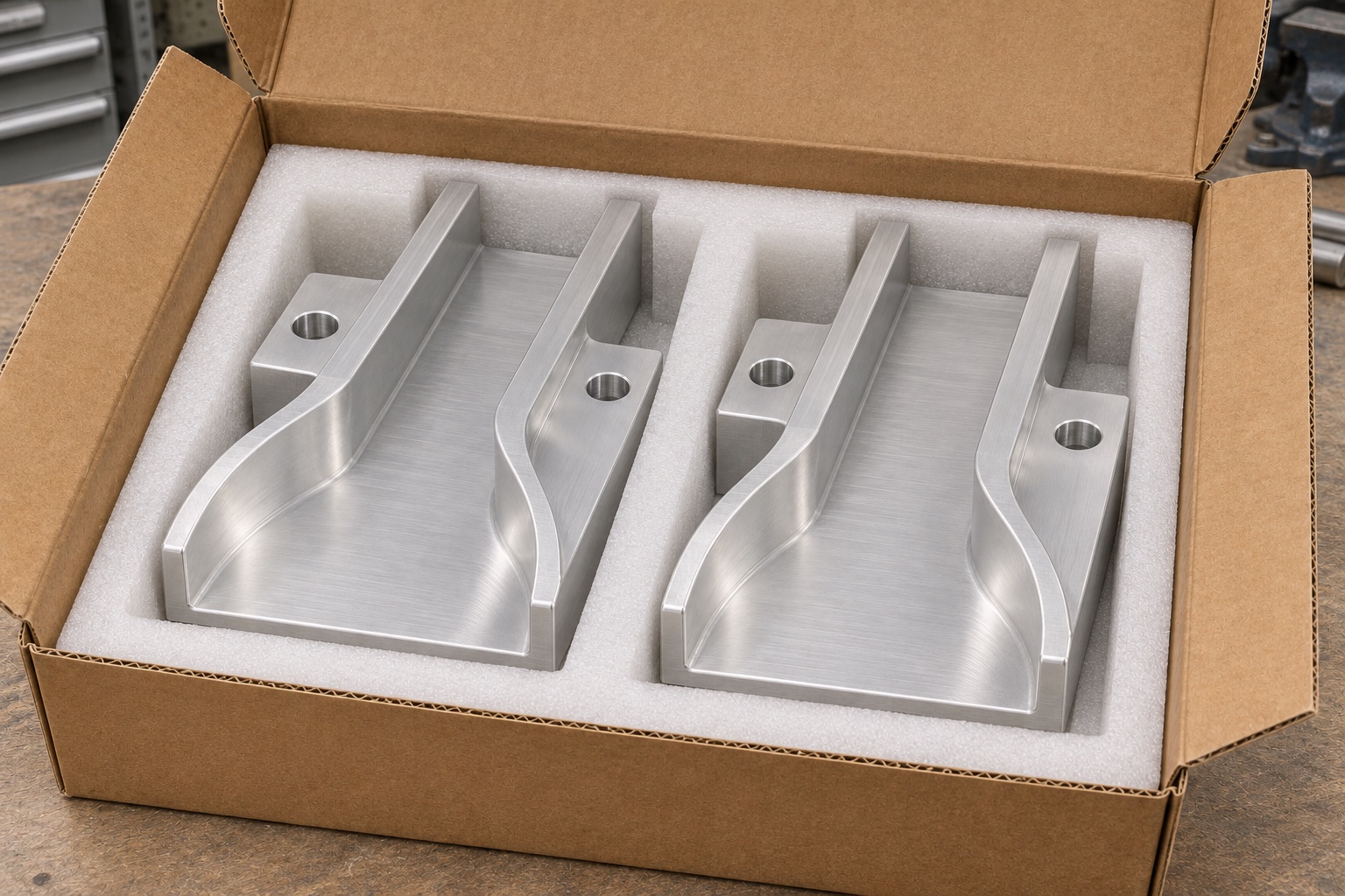
Pack the part without loading the channel walls
Use divided pockets or individual wraps that support the outside and keep adjacent parts off the floor and flared edges. Avoid applying adhesive to working surfaces or filling the channel with loose packing. Label the outer container with part identity, drawing revision and material lot. If the receipt condition includes a specific cleanliness requirement, agree on the process and verification before the order is released. This is ordinary protective packaging. It preserves the documented condition in transit but does not establish that the part is sterile, particulate controlled or suitable for specimen contact.
Establish who approves the assembled system
The machining order can specify a verified mechanical part and an agreed fit trial. The equipment owner must decide how the assembled capper is tested with the specified closure, feed settings and adjacent guides. The drawing, method and acceptance rules for those tests are not inferred from this example. Maintain a clear boundary between component measurements and process results, particularly when multiple suppliers provide the guide components. A later system change should trigger a review of the appropriate interfaces rather than a blanket assertion that every drawing-conforming chute is interchangeable. No customer, certification or performance result is claimed.
FAQ
What part is included in this example?
Only the machined transition block and agreed component evidence. The upstream guide, feeder, drive, sensor and capping head are separate assemblies.
Which dimension controls a lip at the join?
Inspect the floor elevation from the mounting reference and the installed relation to the adjoining guide. One channel-depth reading cannot establish the assembled step.
Does the capper use a specific commercial cap?
The case is generic. The applicable cap envelope and allowed orientations must be defined by the responsible design owner for any actual order.
Why measure the flare away from the ends?
The intermediate curve can have a local narrowing or a profile shift. Both endpoint widths can pass while a cap still catches between them.
Can this part be called clean or sterile on delivery?
Not from the proposed protective packaging. Any controlled cleanliness or sterile requirement needs a separate documented process and acceptance evidence.
What happens if the bench fit and measurements disagree?
Check the fixture revision, contact location, measurement references and sample envelope first. Hold the part until the disagreement is resolved under the approved procedure.

tanghangyun@oemach.com