
Set the prototype scope
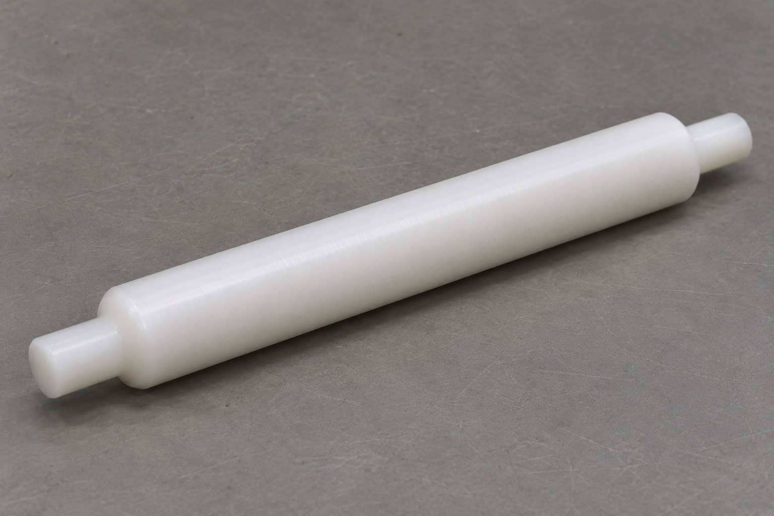
This representative machining case proposes a natural POM-C paper roll spindle for a generic vital signs recorder. It is not a customer delivery, an approved spare or a tested device configuration. The drawing would describe a solid cylindrical body with two coaxial end journals and defined shoulder transitions. The body supports a separate roll core; the shorter journals rest in a holder. The order covers the component, agreed inspection and ordinary protective packaging. Paper selection, drive behavior and recording performance remain outside the proposed manufacturing order.

Review the mounting cross section
Request the holder drawing, support widths and the core and roll envelopes. Mark the journals that rest on the supports and identify what sets end play. Review whether the spindle is introduced at an angle, whether one side must enter first and whether a rounded shoulder can interfere with a square support corner. Record the difference between minimum usable journal length and nominal end projection. If a holder sample is supplied, record its revision and distinguish a fit observation from a variable dimensional measurement. Resolve drawing conflicts before toolpaths are released.
Prepare identifiable POM-C stock
Select round stock of the exact specified grade and condition. Transfer lot identity to the traveler and keep it with the cut pieces. Inspect for surface damage and adequate stock allowance near both journal positions. Agree how the trial piece will be conditioned before final measurement if the drawing is sensitive to time or temperature. Do not substitute another white polymer based on appearance. This example uses POM-C to describe a machining route, not to infer exposure resistance or long-term behavior in a device that has not been evaluated.
Establish the first journal and roll body
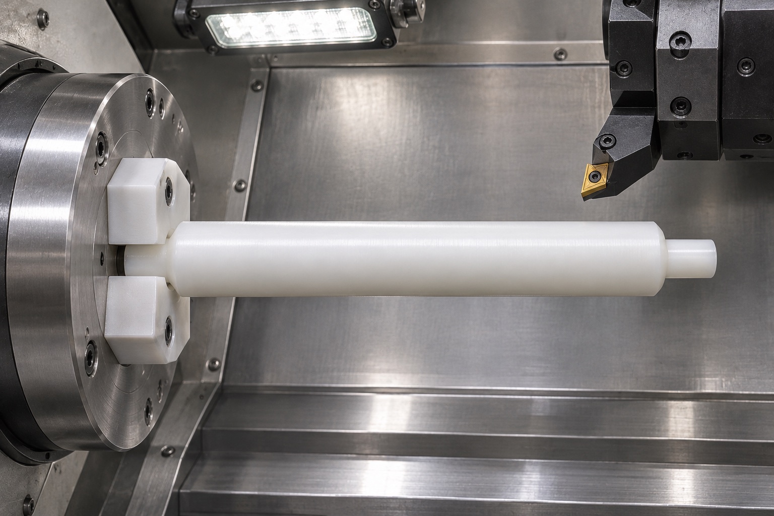
Face one end and turn the first journal, shoulder and accessible roll body while the blank is suitably supported. Leave the opposite end with enough allowance for the second setup. Check the relationship between the first journal and body while the setup remains available, but reserve final acceptance for the drawing-specified condition. If the blank requires additional support, choose a method compatible with the end geometry; do not add a center hole without approval. Record cutting tool condition and any surface marks that could affect contact with the roll core.
Finish the second journal from a controlled reference
Reverse the part using clean soft jaws or a suitable fixture that protects the completed body and locates it from the intended reference. Check seating against the axial stop and confirm concentric setup before finishing the remaining shoulder and journal. Avoid compressing the polymer to eliminate apparent movement. Finish the end length and check that both end faces are clear of burrs. A fixture that grips the body on a cosmetic band may not reproduce the journal reference used for inspection. Record the transfer method so any runout change can be traced to the appropriate setup.
Inspect edge conditions before comparing fits
Check both shoulder transitions, journal ends and the cylindrical support area. A small sliver at a journal entry can make a good shaft bind; excessive hand blending can instead reduce the actual length of engagement. Inspect the transition using the agreed visual or dimensional method. Remove loose material without scraping the working diameter. If the drawing calls out a radius, verify it separately from the nominal step length. Identify which defects can be corrected within the original limits and which need a disposition. Do not rework a questionable part only until one convenient holder accepts it.
Measure the journal stack on the first piece
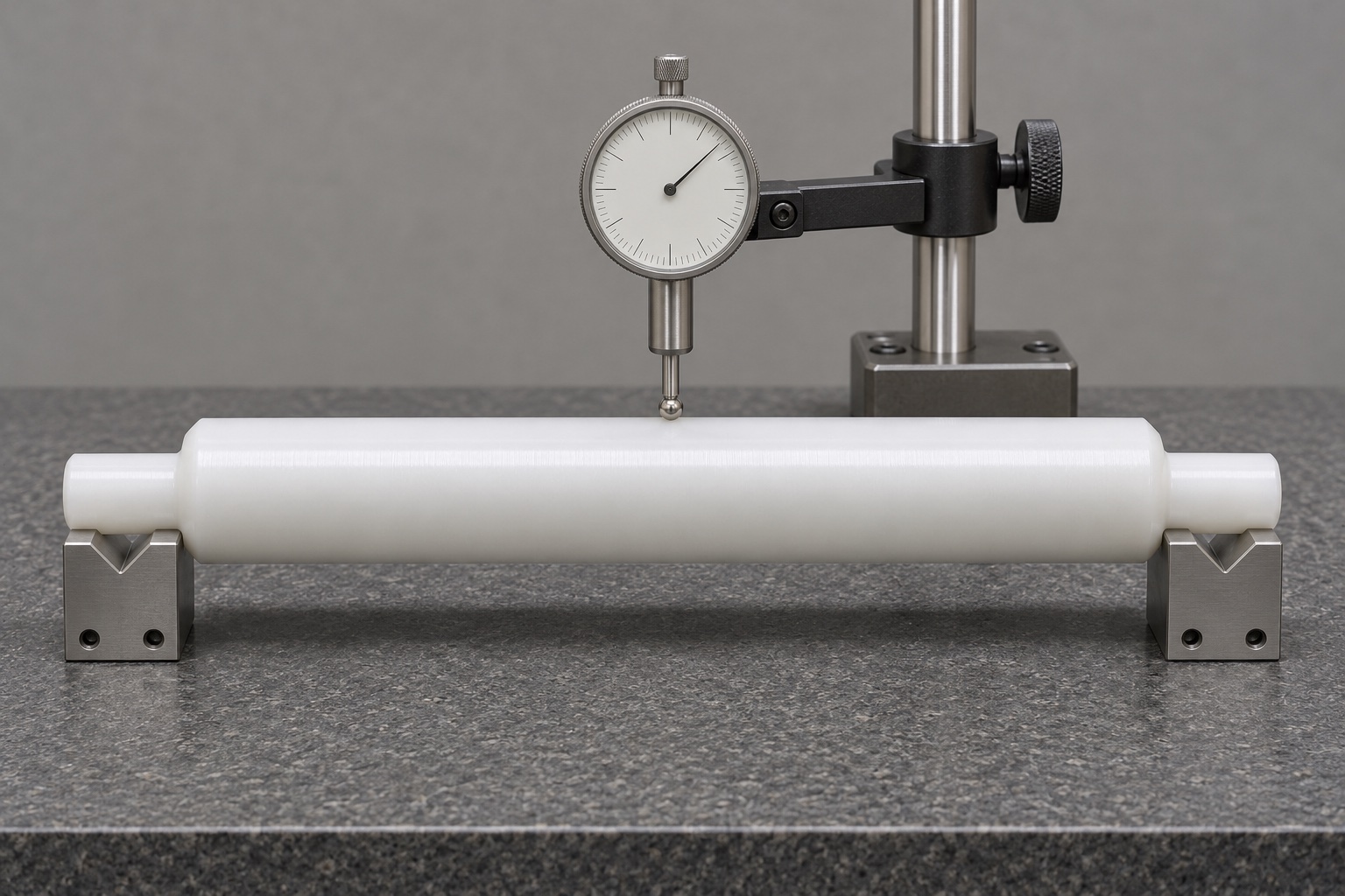
In the released condition, measure the journal diameters at suitable axial and angular locations. Record the shoulder spacing, body diameter and end projections from their specified references. If the drawing requires runout, support the shaft by the defined journals and measure at the prescribed sections. Check that contact force and support movement do not dominate the result. Report values with the measurement setup, instrument and stock lot. An inspection photograph is useful context, but the decision should rest on actual results and the uncertainty of the method rather than on a visual impression of straightness.
Build a representative roll-core trial
A fixture can use two drawing-controlled supports and a clean core surrogate. Place the spindle as intended, observe journal seating and verify that the core can occupy the allowed axial space. If the roll is meant to turn on the body, record whether there is interference in the fixture without applying abnormal force. Document which core and support conditions the fixture represents. Do not infer print quality or paper transport performance from a hand rotation. The equipment owner defines the approved assembly test and verifies the actual recorder with its paper, drive and software configuration.
Diagnose taper or binding before changing offsets
If body diameter varies along the length, compare readings made after unclamping and check support, tool condition and cutting pressure. If the second journal alone shows runout, review the transfer and stop seating before changing diameter offsets. When the roll core binds at a shoulder, inspect its edge condition and the radius against the drawing before shortening the spindle. Segregate affected pieces and obtain approval for any change outside the released limits. Record the corrected operation and repeat the inspection that found the issue. This preserves a traceable route for the next prototype rather than an undocumented adjustment.
Define release evidence by component, not device
For a small lot, agree on actual first-piece values, material identity, final visual condition and any optional fixture observations. Specify which measurements are repeated and when a renewed first-piece check is required. If the proposed route changes after the trial, record the affected revisions and parts. The report should not claim that a dimensional result validates use in a patient monitor. A quote for custom CNC turning can separately price the spindle, fixture, inspection and packaging. Specify how open requirements, such as a special cleaning or handling condition, will be resolved before release.
Control the repeat order and mating revisions
Confirm that the holder and core drawings still correspond to the spindle revision before ordering another lot. A replacement roll or revised support may affect fit even though the machined part is unchanged. Check whether stock, tool or fixture substitutions need prior review and which measurements must be repeated after such changes. Retain records that distinguish the accepted first piece from later production. The example provides a decision path and inspection plan, not actual capability data or a commitment that a particular production lot has been made. The drawing owner retains responsibility for product-level acceptance.
Pack the spindle on its body, not its ends
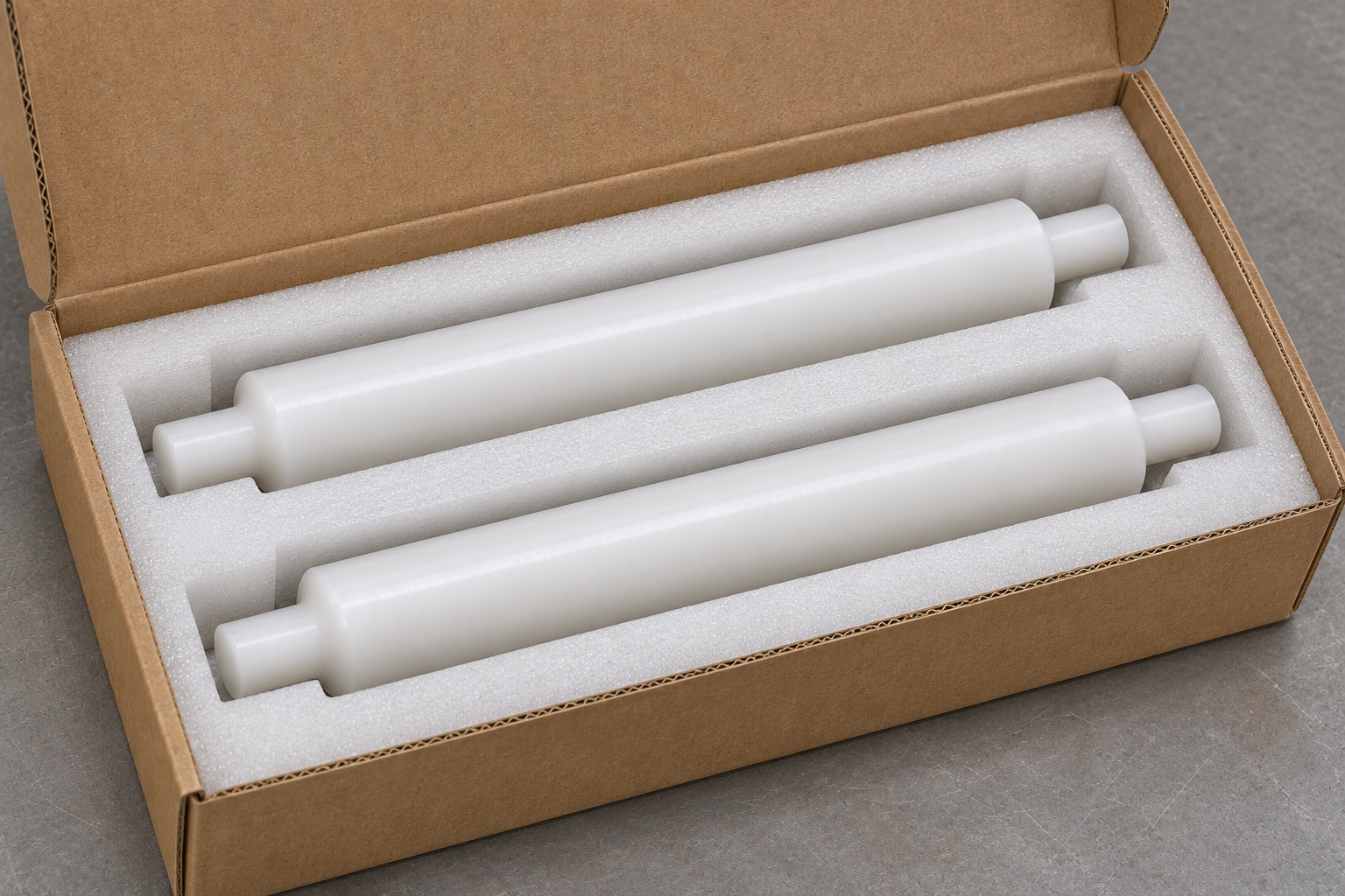
Use a divided tray or individual protective wrap that supports the long body without bending it. Prevent journal ends from striking another part or the carton. Avoid tape on the working surface and keep loose particles out of the package. Put the lot and drawing revision on the container and link them to the first-piece and inspection records. If the order requires a separate controlled cleanliness state, define the handling and acceptance criteria before shipment. Ordinary protection is not a sterile barrier, and it does not qualify a part for any clinical application.
FAQ
Why use two setups for the shaft?
They can provide tool access to both ends without leaving an unmachined grip feature. The second setup must preserve the geometry specified relative to the finished journals.
Is this a verified recorder replacement?
No. It is a representative component and machining plan, not a named spare, approved installation or actual customer delivery.
What is the best check for a binding core?
Identify where contact first occurs, then compare core envelope, body diameter and shoulder geometry against their drawings. Do not diagnose every bind as a diameter error.
Can soft jaws eliminate polymer distortion?
They may improve support and protect surfaces, but pressure and support still matter. Check the released geometry with a repeatable method.
Does the prototype include print testing?
No. The trial covers defined mechanical conditions. Print tracking and recorder output need separate validation on the actual equipment.
How is traceability maintained?
Record the material lot, drawing and process revisions, inspection results and package label together. Keep changes and reinspection evidence linked to the affected pieces.

tanghangyun@oemach.com