
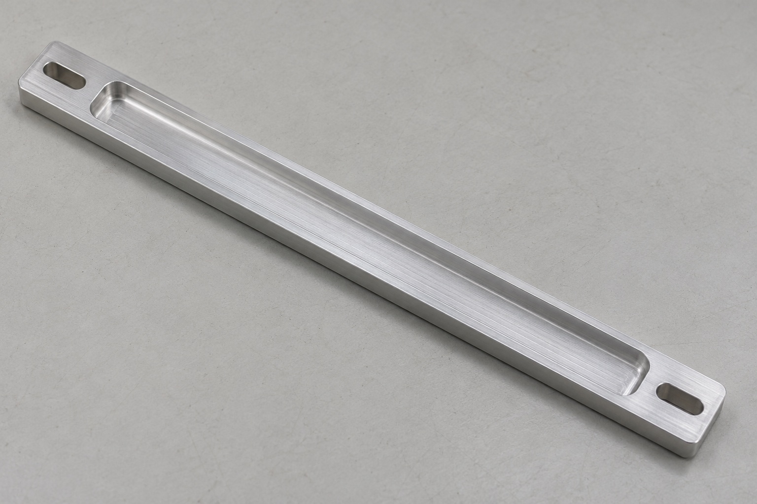
Describe the carrier and the proposed order
This representative machining case describes a proposed 6061 aluminum plate for mounting an auxiliary height reference strip on a generic slit lamp upright. It is not a delivered order or an approved spare for a particular device. The plate has a long shallow rectangular recess with radiused internal corners and two oblong through slots. One slot is at each end of the plate. The slots let the assembly position be adjusted within the drawing limits. The component order covers the bare carrier and agreed finish and inspection. It does not include the strip, calibration or clinical verification.

Review the upright and strip before machining
Obtain the drawing revision for the plate and the mating envelopes for the upright, strip and fasteners. Identify the rear mounting plane, the end used for longitudinal measurements and the side that establishes lateral orientation. Confirm where the strip should bear and whether any attachment layer is included in the recess depth. Check how the screw heads fit near the two ends of the strip and whether a tool can access them at the allowed settings. List unresolved limits on the manufacturing review rather than deciding an installation value on the shop floor.
Select stock and keep the identification with each blank
The proposed route uses identified 6061 stock in the condition stated on the released drawing. Cut blanks with sufficient allowance for the rear face and the long sides. Record the lot or stock reference before the blanks leave the cutting station. Examine the blanks for surface defects where the finished pocket or visible face might remain. If the order includes anodizing, obtain the final dimensional requirements and allowed marks in advance. The machining plan should not assume an appearance, coating thickness or exposure resistance that is absent from the specification.
Establish reference surfaces on supported stock
Support the long blank along its length without forcing it into a false flat condition. Face the rear mounting surface and establish a long side and an end reference. Remove chips before reseating the blank for the next operation. Check the datum repeatability by releasing and seating the trial blank again. Record where the part is supported and where the clamp force is applied. If the rear face will need finishing later, plan the reference transfer so the final recess elevation can still be verified. Do not locate critical features from a changing saw edge.
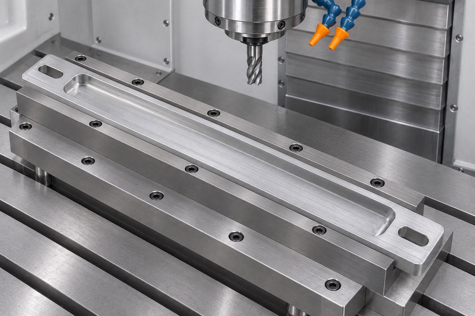
Rough and finish the long recess
Rough the shallow pocket while the blank remains supported, leaving a controlled finish allowance. Recheck the released shape if the blank moves enough to affect the final cut. Finish the floor and side surfaces without forcing the part flat. Use a cutter that can produce the allowed internal radii, then compare those radii with the actual strip corners. Keep chips from being dragged across the floor during finishing. Before changing the cutting offset, verify that the measured depth comes from the designated reference and that the probe is sampling the floor rather than a wall radius.
Machine the two slots and clear their edges
Mill the oblong openings from the same longitudinal reference where the setup permits. Provide exit clearance and support near each end to avoid a torn edge. Check slot width, length and relative location independently; a slot can be the right length and still shift the available adjustment range. Inspect the bottom exits for burrs that could make the carrier rock on the upright. Use only the specified edge breaks at the openings. Do not enlarge the slots to make a particular set of hardware fit unless the drawing owner approves the change and the new fit is verified.
Keep finish requirements tied to the final condition
Before any surface treatment, verify the geometry required at the intermediate stage. If a finish is specified, protect the mounting face and recess from handling damage and document the lot through the finishing process. Inspect the final slot clearance and strip recess where the drawing applies after finishing. A finish color check does not replace dimensional or surface acceptance. If there is an unapproved variation, segregate the part and refer it to the drawing owner. Do not mechanically remove coating from a working surface to recover fit without authorization.
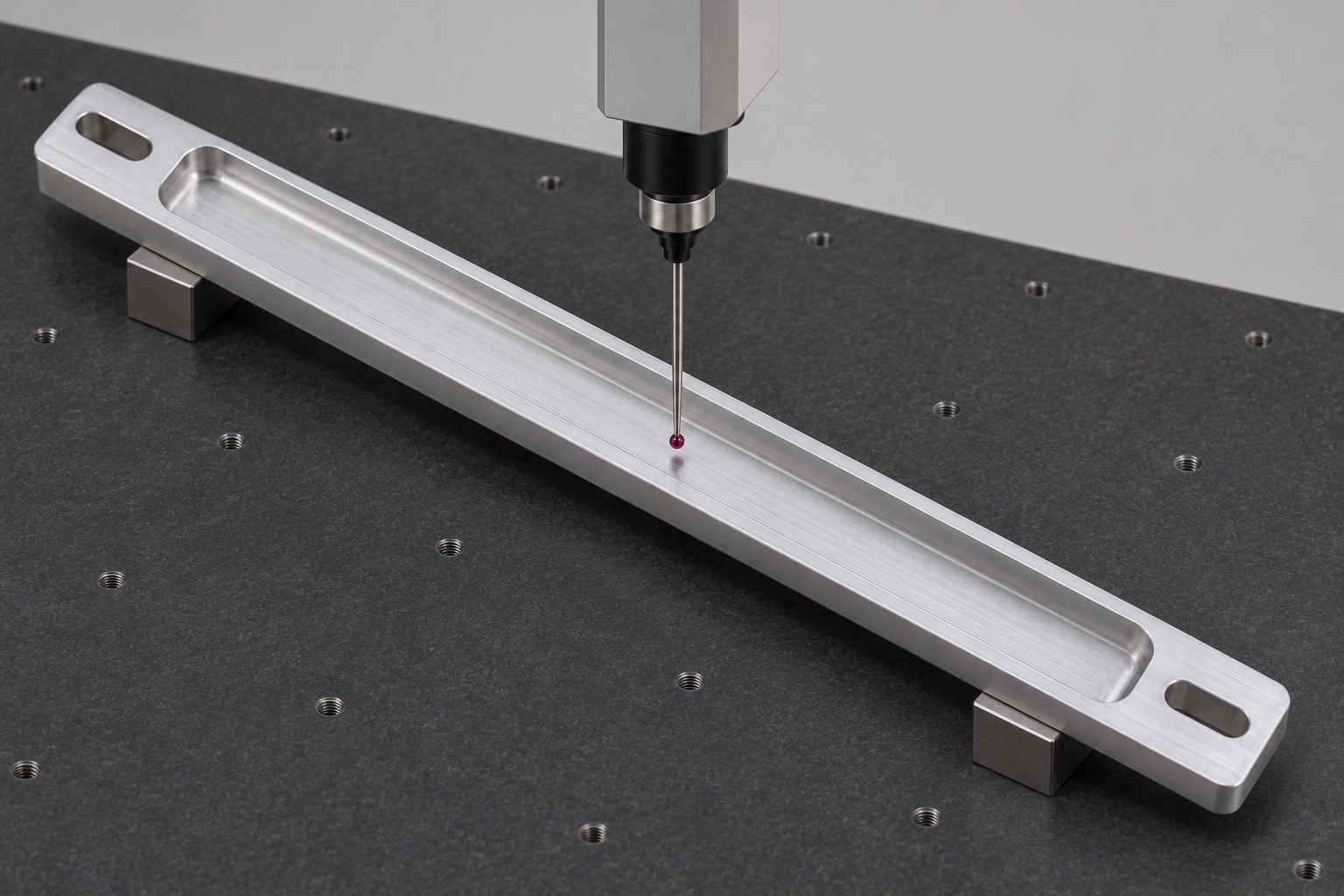
Inspect the free-state shape and pocket separately
Support the plate as specified without applying force that would straighten it. Check rear flatness or profile and measure the recess height or depth from its drawing reference at several locations. Inspect both slots using a method that resolves the radiused ends and the parallel sides. Confirm that the instrument can reach the working floor without an oblique contact on the wall. Document the supports, instrument, revision and actual readings. If the drawing requires a mounted shape as well, record it under the controlled mounting condition rather than merging the two results.
Trial the installation with unmarked mating parts
Use a mock upright and a blank strip representing the relevant revision. Assemble the plate with the specified hardware under the agreed bench condition. Check that the strip seats on the intended support and that the carrier can travel through the required mechanical adjustment range without hardware interference. Record the position of any first contact and the fixture limits. Do not add calibration markings to infer system alignment. The result is a fit observation, not a demonstration of reference accuracy, patient positioning or optical performance on a complete slit lamp.
Investigate fit failures in the correct order
If the carrier rocks on the mock upright, inspect the rear face, slot exit edges and fixture condition before changing the recess. If the strip seats at one end only, compare the corner radii and depth along the pocket. If adjustment travel is short, separate hardware envelope, slot geometry and fixture alignment. Hold affected parts until the cause and permitted action are agreed. Record any approved change in the drawing or traveler and repeat the corresponding checks. Do not use a successful hand adjustment on one sample as evidence that the repeat route meets the released specification.
Define the evidence for prototype and repeat lots
Agree on stock identification, first-piece dimensions, finish record if required and any limited fit-trial notes. Identify which changes to stock, tools, fixtures or finishing trigger a renewed review. For a repeat lot, confirm that the strip and upright drawings have not changed independently of the carrier. Quote any dedicated supports, reference fixtures or additional inspection explicitly. This case describes a proposed method only; it does not report actual production data, certified compatibility or acceptance by a customer. Assembly alignment and device qualification remain the equipment owner's responsibility.
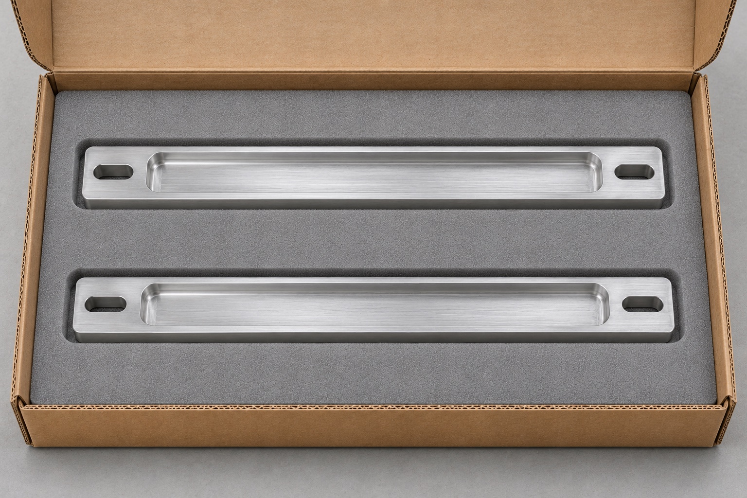
Keep the carrier flat and protected in transit
Place carriers in separate long pockets or use a straight, nonabrasive support with a divider between parts. Do not load the pocket floor with packing material that can scuff it or put tape across the slots. Identify the part, lot and drawing revision on the container and link them to the inspection report. If the receipt inspection has appearance requirements, protect the defined visible surfaces and agree on handling. The example uses ordinary nonsterile packaging. It preserves the inspected condition without implying a controlled clean environment or a validated sterile barrier.
FAQ
What does the proposed order include?
It includes the mechanical carrier and agreed material, finish, inspection and protection. It does not include an assembled scale or an instrument calibration.
Can a long slot be checked with a pin alone?
A pin may help verify width under a defined gauge method. It does not establish slot length, end radii or position from the mounting references.
Why support the plate when measuring flatness?
Use the specified supports to obtain repeatable readings without straightening the part. If the mounted condition matters, inspect it separately under its own approved setup.
Is the recess checked again after anodizing?
If the drawing applies to the finished condition, check affected recess and slot dimensions after processing. Document which readings apply before and after finishing.
What does a mock upright trial verify?
It checks the specified assembly interfaces and mechanical movement under the fixture conditions. It does not verify the position of the instrument's height reference.
Is this a customer delivery case?
No. It is a representative CNC machining route with proposed acceptance evidence, not a statement of actual delivery, certification or product performance.

tanghangyun@oemach.com