
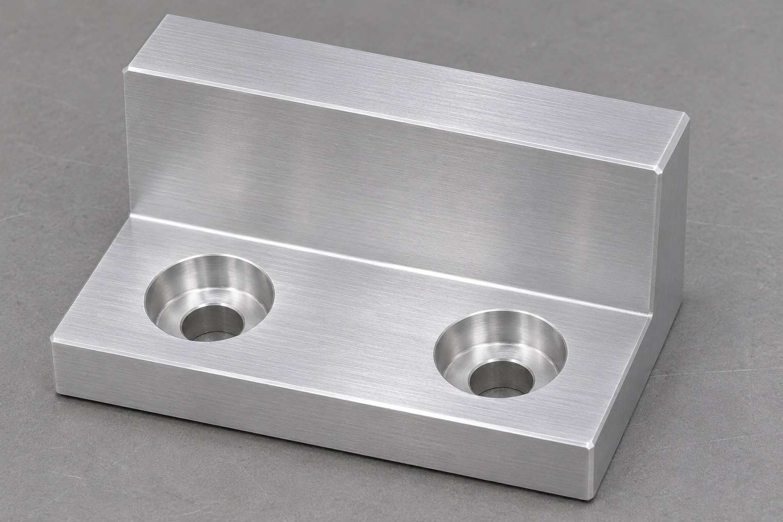
The order is for a mechanical stop block
This representative machining case describes how a small lot of 6061 aluminum end stops could be made from a controlled drawing for a generic ultrasound equipment accessory rail. It is not an actual customer delivery or an approved replacement part. The block has a flat mounting foot, a raised shoulder facing an approaching tray and two counterbored holes in the foot. The working shoulder sets the end position. The machining scope is limited to the block, its finish and agreed inspection. No braking, impact, load rating or transport restraint is claimed for this component.

Start with an interface review
Ask for the rail cross section, the tray approach envelope and the fastener specification along with the part drawing. Mark the base that seats on the rail and the side or step that sets the block's position. Confirm the face that should contact the tray first. Review where the mating rail corner passes the machined step, because a drawing that shows two nominally square corners may not provide space for a practical cutter radius. Any proposed relief or change to the mating corner belongs on an approved revision before the prototype is machined.
Select stock and identify the functional allowance
Use stock that meets the approved 6061 grade and condition. For the example, a rectangular blank provides enough material for the full shoulder and foot. Allow machining stock where the base and locating face need to be finished, and mark the material identity on the traveler. If anodizing is required, establish which final dimensions include the coating, where it may be masked and which marks are allowed. Do not change the raw cut size on an assumption about coating thickness. Seek process data and verify actual dimensions when the requirement applies after finishing.
Establish repeatable references in the first setup
Face the bottom and finish a side reference that can be used in the next setup. Support the block on clean parallels and keep clamps away from future contact surfaces. Check that a reseated trial blank returns to the same position without rocking. Use an end stop or other defined fixture reference to control the block length as required by the drawing. Note which side faces are references and which are only external boundaries. The location of the working shoulder should not depend on touching a rough saw edge that varies between blanks.
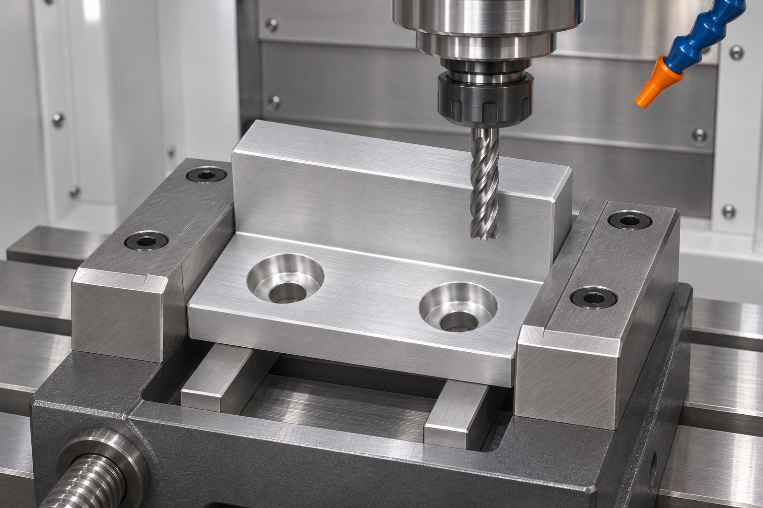
Mill the shoulder and foot as a linked operation
With the base and side referenced, rough the stepped shape and leave stable stock for finishing. Finish the vertical shoulder and adjacent flat foot, preserving the specified contact band. The corner transition may need a separate tool or relief if the mating design calls for it. Check that the step and the rear face have enough support during finishing to avoid vibration marks. Measure the shoulder position on the first released part before applying a tool offset. A dimension measured from the wrong origin will not improve when the cutting offset is adjusted.
Cut the mounting holes and counterbores
Drill the two clearance holes in the foot, then machine the recessed seats to suit the specified fasteners. Support the underside during breakthrough and provide space for chip removal. Check seat depth against the final drawing condition, and inspect the floor for damage or remaining burrs. At trial assembly, verify that the specified screw head remains out of the accessory's swept envelope without forcing it below the seat. Do not infer screw engagement or preload from that check. Those are assembly requirements and must be evaluated using the actual hardware and approved installation procedure.
Deburr the rail side without moving the datum
Inspect the hole exits and base edges after machining. Remove burrs in the manner allowed by the drawing, especially where a raised lip could prevent seating. Keep a controlled edge break at the contact plane so a chamfer does not remove the stop surface. If a drawing specifies a corner relief, verify its geometry separately instead of relying on hand blending. An observed gap at the base can come from a burr, a corner collision or an uneven part. Record the location and repeat the check after cleaning before proposing any dimensional change.
Inspect the geometry and record the reference setup
For the first piece, verify the mounting base, shoulder location and its orientation from the drawing datums. A suitable coordinate measurement or fixture-and-indicator method can compare the face at several accessible points. Avoid sampling the chamfer or a radius when assessing the plane. Record counterbore depth and the through-hole pattern as separate characteristics. Check the condition before and after finish where the order requires it. Keep the actual measurements and the relevant instrument reference, not just a pass mark, so the result remains usable when the rail or finish specification is reviewed.
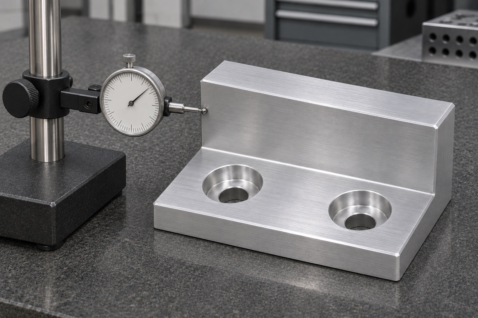
Run a defined bench fit, not a load test
Mount the block on a controlled rail segment using the designated hardware and installation conditions. Move a mechanical tray surrogate through the last portion of its travel and observe where it first touches. Inspect screw-head clearance and check that the block stays seated for this unloaded trial. Record the geometry represented by the fixture, plus any limits such as a single rail revision or one tolerance condition. Do not extrapolate the observation to equipment retention or impact performance. A complete ultrasound cart or accessory assembly requires its own design review and any necessary qualification.
Resolve deviations before release
If the tray contacts a screw head first, examine the hardware envelope, recess depth and rail alignment instead of immediately deepening the counterbore. Reducing floor thickness may violate the design. If the shoulder position is incorrect but the hole pattern passes, review the machining datum and the mating reference before changing the program. Segregate affected pieces and record the scope of any approved correction. For a small-batch repeat order, define when to run a renewed first-piece inspection after changes to the fixture, stock, finishing supplier or machining program. Do not treat an undocumented trial adjustment as an approved production method.
Provide a traceable prototype handoff
List the drawing revision, material identification, first-piece evidence, finish condition and the limited fit check in the release package. The quote should distinguish those deliverables from fixtures, specialized cleanliness and additional testing. Mark unresolved interfaces rather than pricing a general guarantee. If the equipment owner later changes rail profile or fastener, revisit the mechanical stack before reordering. This plan is meant to show how a custom 6061 CNC milling request for a medical equipment part can be turned into measurable requirements without inventing tolerances, inspection results or compatibility for an unspecified system.
Package without loading the working shoulder
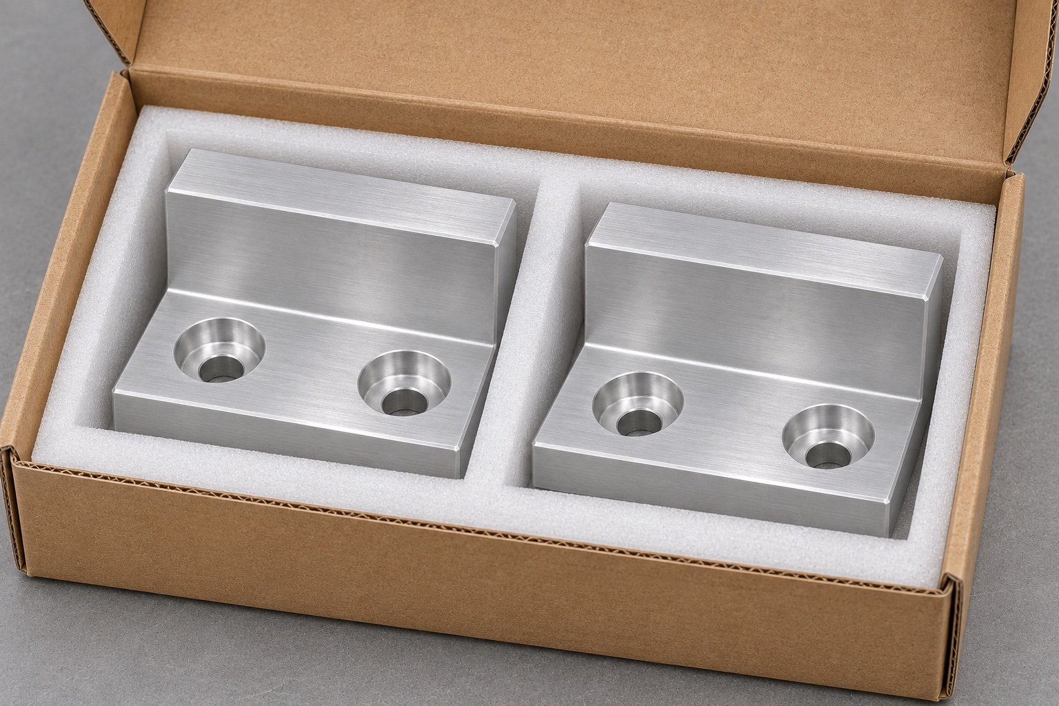
Pack each block in a divided tray or suitable individual wrap so the raised shoulder cannot score another block's base or trap abrasive debris. Keep labels off the working surfaces and link the outer label to the part number, lot and revision. If finish appearance has acceptance criteria, select packaging contact points accordingly and confirm the inspection at receipt. The proposed packaging provides ordinary transit protection. It is not a sterile barrier, a cleanliness certificate or a substitute for any handling conditions defined by the equipment owner. Preserve the first-piece identity if the order requests it.
FAQ
Is this a commercially qualified ultrasound cart component?
No. This is a representative machining example for a proposed drawing-controlled block. It does not identify a customer, approved product, delivery or validation result.
Why use two recessed holes in the foot?
The recesses make room for designated screw heads outside the accessory's travel envelope. The approved drawing and hardware determine size, depth, support and any final clearance checks.
Does coating thickness matter at the locating step?
It can affect the assembled clearance if the step is coated. The drawing should state the required final condition and whether masking or another approved process control is allowed.
What should the first-piece report measure?
Include the working shoulder relative to the mounting datums, the locating geometry, mounting-hole pattern and recessed seats. Record the instrument, setup and whether the check was before or after finishing.
What does the fixture slide check prove?
It documents the observed approach, first contact and screw-head clearance under the specified fixture conditions. It is not a retention, impact, load capacity or transport test.
Can a machinist deepen the counterbore to solve interference?
Only through an approved drawing change or disposition. First identify the source of interference, then confirm that the revised recess leaves the required support and floor thickness.

tanghangyun@oemach.com