
Define a mechanical prototype order
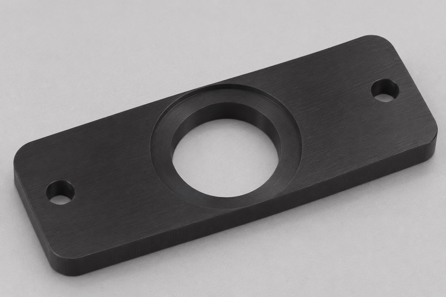
This representative machining case describes a proposed black PEEK carrier for a filter position in a laboratory microplate reader. It does not document a customer delivery, an approved substitute or an instrument test. The drawing would show a rectangular plate with two end clearance holes and a stepped central opening. A separate filter rim rests on the annular step; the smaller through opening leaves the required path unobstructed. The order is for the carrier only. Acceptance of a prototype concerns dimensions, surface condition and a defined mechanical trial, with optical evaluation outside the component order.

Lock the interface revision before cutting
Obtain the instrument-side mechanical interface drawing and the revision of the filter rim envelope. Identify whether the lower plate face rests on a pocket floor, on discrete pads or against another plate. In this example the bottom face and two perpendicular outside edges locate the carrier; its screw holes are clearance features. Transfer that intent to the inspection plan. The filter seat dimensions should describe both the usable flat annulus and its elevation above the mounting face. Confirm that the tool radius allowed at the edge of the seat leaves clearance for the rim.
Use incoming stock that can be traced
The proposed route uses a black PEEK plate grade identified on the purchase specification. Record the stock supplier's identification and the blank orientation in the traveler. Inspect the stock for damage and available thickness before facing. Color is an appearance attribute, not proof that the polymer has a specified filler content, optical behavior or cleanliness. If the design calls for environmental evidence, resolve that request before quoting the lot. Avoid substituting another dark plastic when stock is unavailable: any material change needs the drawing owner's review and may change machining, fit and handling.
Establish bottom and side references
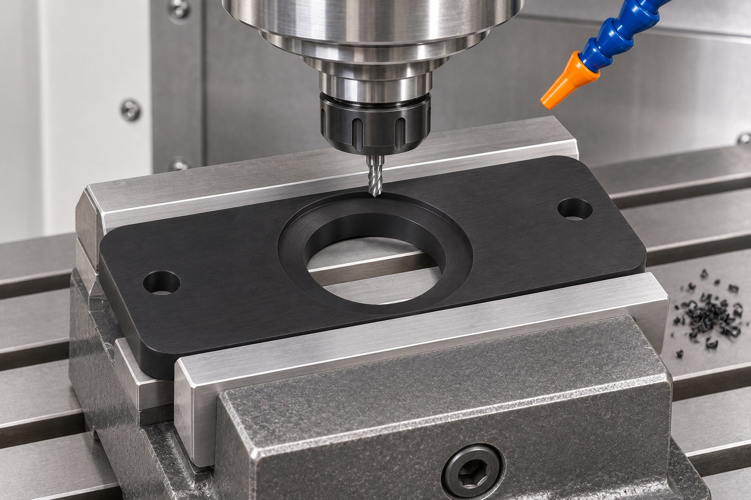
Machine the base face and locating edges with allowance for the subsequent setup. Use broad, clean supports to avoid pressing a thin blank into a false flat condition. Trial clamp placement away from the annular seat and leave clearance beneath the planned through cut. Verify the working offsets from the actual locating edges after reseating the blank. If the bottom surface will later be refinished, plan that transfer explicitly; a nominal depth from the top face cannot substitute for a controlled seat elevation. Record the fixture and clamp setting so later parts can be compared.
Rough and finish the stepped opening
Rough the through aperture with enough material left for a stable finishing pass. Mill the annular recess while the plate is supported, leaving a clean land rather than an unintended tapered pocket. Where the selected tooling and geometry allow it, finish the recess and opening in the same setup. Keep the edge at the bottom of the through cut accessible for controlled deburring. Inspect the first workpiece for smeared polymer, tearing or residual chips before making a size correction. A burr seen in the projected opening can make the initial diameter reading misleading.
Drill the mounting holes without changing their role
Drill the two end holes using the drawing's position and clearance limits. Protect the underside around breakthrough with a suitable support arrangement. Check that the fastener heads and tools have the intended envelope, if that is part of the supplied interface. Do not ream clearance holes to a tighter fit solely to improve a machining report; that may make installation harder. If a trial reveals that the carrier shifts when the fasteners are tightened, investigate the actual locating edges or pocket instead of treating the hole pattern as the alignment reference.
Control burrs and release the part before measurement
After machining, remove loose chips without touching the finished annular seat with an abrasive tool that can round the contact edge. Inspect the seat at a shallow angle and examine the opening against contrasting illumination. Allow the part to settle under the agreed measurement conditions after releasing the fixture. Check the mounting face on a non-distorting support. If it rocks or bows, record the direction and magnitude before altering the program. A repeated free-state deviation across prototypes is evidence to review stock, support and roughing strategy, not simply a reason to tighten the vise.
Use separate inspection records for seat and opening
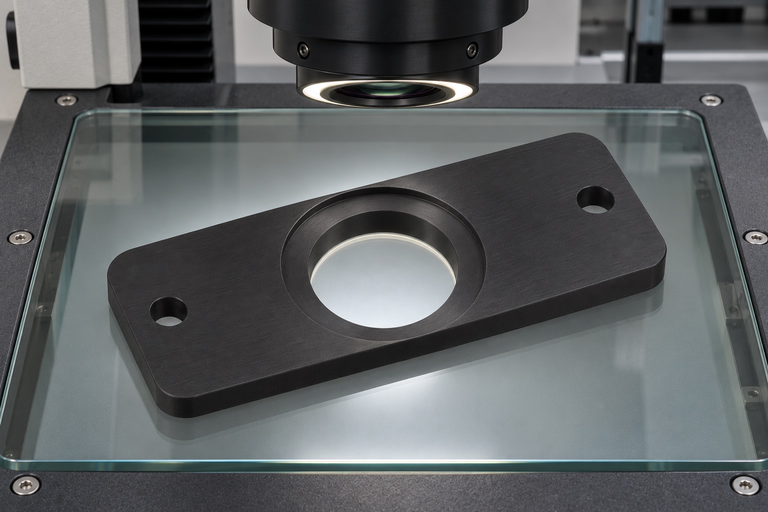
Establish the bottom and side references in a suitable measuring fixture. Use a validated profile or vision method for the clear aperture, making sure the measured boundary is the smaller through opening. Compare the annular seat elevation at several positions using an instrument that reaches the narrow land without contacting the wall. Log the size, position and support condition separately. If the tolerance approaches the uncertainty of the chosen method, agree on an alternative before deciding acceptance. Include the instrument and drawing revision on the first-piece report rather than relying on a photograph of the setup.
Check the seating with a reference rim
A non-optical ring can represent the limiting outer diameter and rim corner for the bench check. Let it settle under the specified load and check that it contacts the seat rather than hanging on the wall radius. If the order includes a retainer, test it only at the stated position and preload. Record any visible gap or contact interference and identify the version of the trial fixture. A ring seating successfully is evidence only for that mechanical interface; it does not show that a real filter is aligned, protected from stress or optically acceptable.
Resolve process risk before a repeat lot
If the first part is dimensionally acceptable but the opening has residual burrs, revisit tool access and the planned edge operation before approving repeat production. If free-state flatness varies, investigate clamping, stock release and the material removal sequence. Record corrective actions with the affected pieces and inspect again after each approved change. A prototype order should identify the characteristics requiring renewed first-piece checks after tool, fixture or stock changes. Do not publish a capability claim from the trial itself; a repeat order may use a different lot of stock or a revised machining setup.
State quote inputs and deliverables
The drawing and model should agree on the recess, central opening, outside locating edges and hole pattern. Quote the machining, agreed inspection, any fixture and packaging against the same revision. State whether the request includes visual criteria for particles or marks on the seat and how those are assessed. For an initial prototype, include a marked drawing or report showing the measurements and any assumptions. The order remains for custom CNC machining of a mechanical carrier. It is not a quote for optical calibration or a claim that the part is validated for diagnostic use.
Pack the plate without loading its working seat
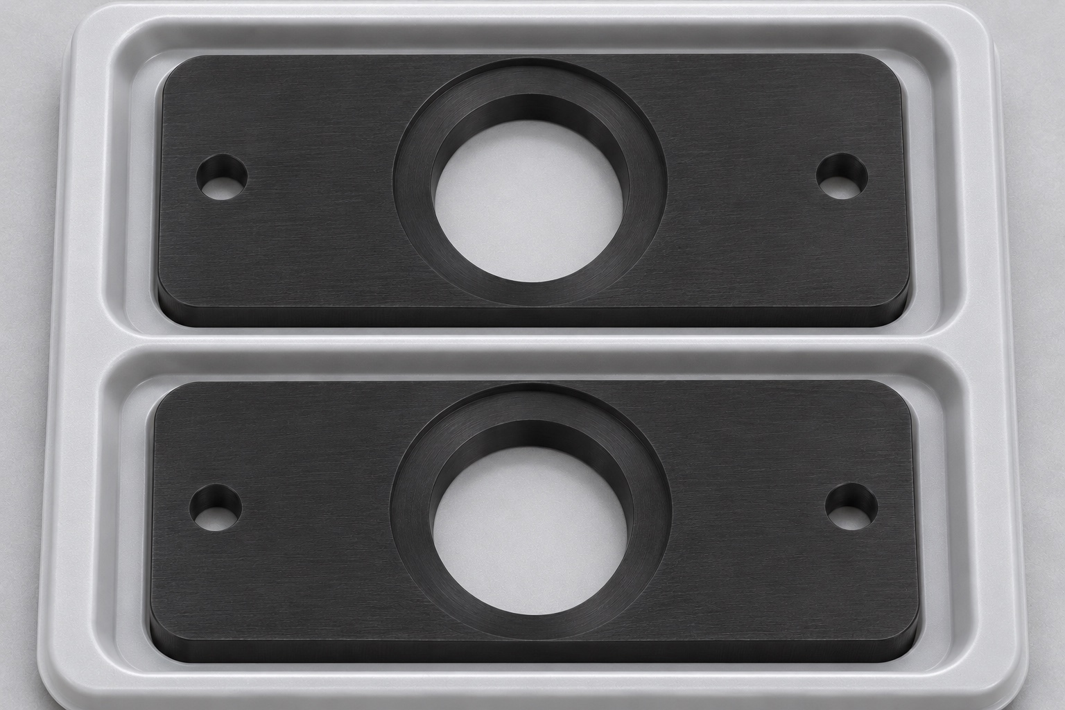
Place each carrier in a separate tray pocket or compatible individual protection. The pocket should locate approved exterior surfaces and keep stacked parts from bearing on the annular seat. Do not tape over the aperture or use a loose spacer that can scratch it. Use a package label tied to the material lot, part revision and inspection record. If special cleanliness is requested, the owner should specify the handling and acceptance protocol before release. The ordinary protective packaging described here is not sterile and makes no claim about particulate levels.
FAQ
Why not locate this carrier from the screw holes?
In this proposed drawing the holes provide fastener clearance. The bottom face and side edges locate the part. A different mounting architecture can use holes for location if the drawing and mating features define that explicitly.
Can one image measurement establish both diameters?
Only if the method reliably distinguishes the opening and the larger recess edge under their respective lighting and focus conditions. The measurement plan should identify each edge separately and verify the resulting uncertainty.
How is seat depth related to installed filter height?
Installed elevation depends on the seat relative to the mounting reference, not merely depth below the top face. The dimensional stack includes any variation in thickness and interface contact.
Why does this case use a non-optical ring?
The ring can represent rim size and corner geometry without using a fragile coated filter during an early trial. It does not replace evaluation of a real optical element or its installed performance.
Does black PEEK establish low stray light?
No. Appearance does not specify optical properties. If the equipment design needs a stray-light limit or a surface requirement, define the relevant measurement and assess it separately.
What evidence accompanies this example?
The case describes a proposed traveler, dimensional report, fit trial and packaging plan. It does not claim a measured lot, a customer result or a completed delivery.

tanghangyun@oemach.com