
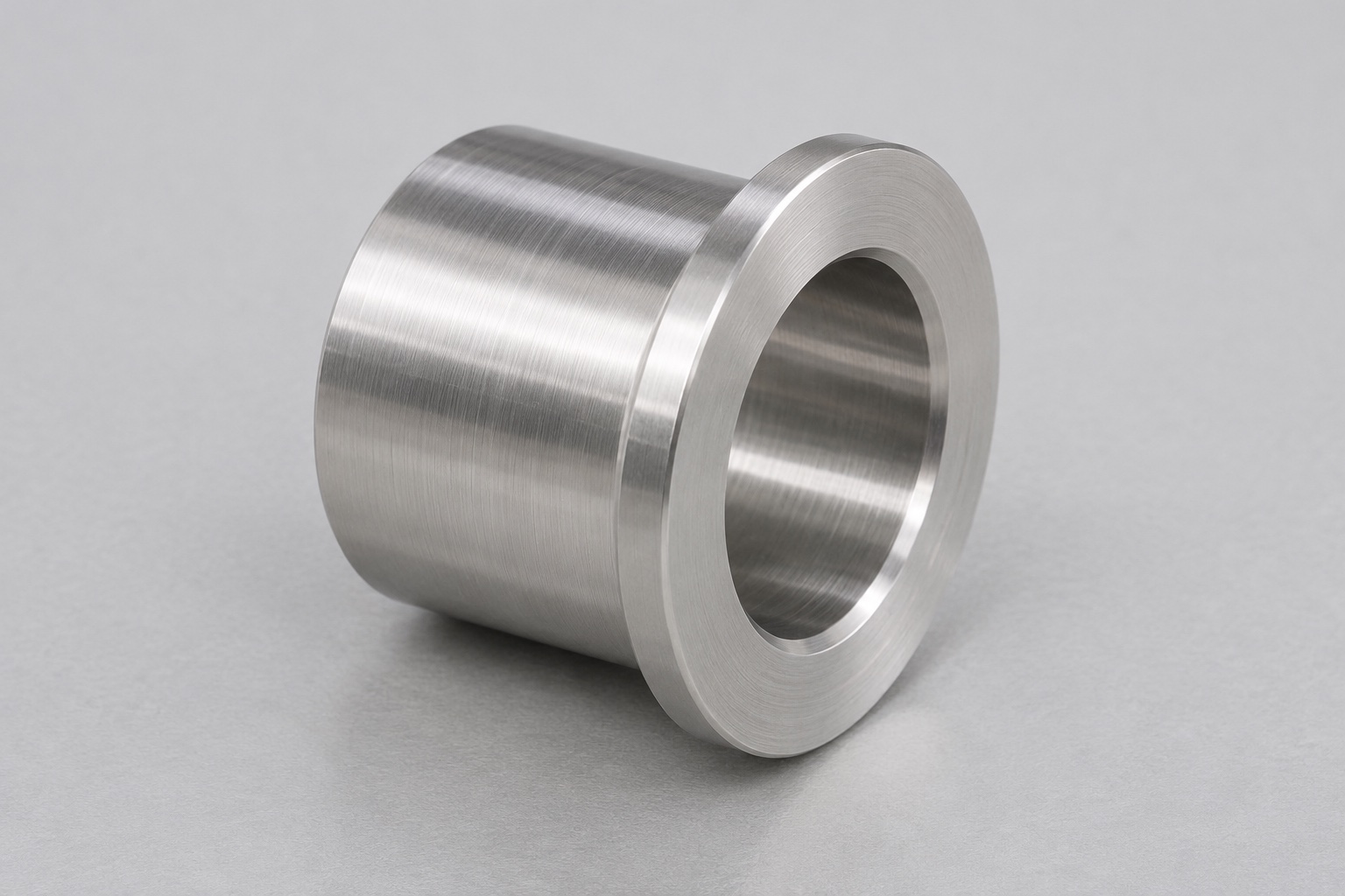
The proposed part and order
This representative machining case concerns a flanged spacer sleeve for a medical instrument washer-disinfector support stack. It is a manufacturing example, not a customer delivery or a replacement part for a named machine. Imagine a request for a small batch from a released drawing. One axial face seats against a bracket; the opposite face defines an offset in the stack. The central through bore clears a mating shaft. The proposed order covers turned geometry, agreed finish and documentation. It does not include a bearing, seal, spray arm, or evidence of cleaning performance.

Turn the assembly description into a review drawing
Before quoting, mark the bracket-facing annulus and the opposite working end. Use those marks to identify the length that sets the offset and distinguish it from any machining relief. Identify whether the shaft has a radius near its shoulder that the bore entry must clear. On the external flange, retain enough width for contact after deburring. Request the mating shaft and bracket envelope at their limiting sizes rather than designing a fit around one sample. The output of this review is a list of controlled features and open questions, not an undocumented revision to the supplied geometry.
Select and record the starting stock
The example route starts from 316L round stock sized to leave a finishing allowance on the flange. Check the stock description against the drawing and connect incoming identification to the traveler before any bar is cut. If the order needs a material test report, verify its linkage to the stock actually issued. Keep an offcut or material identifier only as required by the agreed traceability plan. A shop cannot infer a finish requirement or detergent resistance from the word stainless. The drawing owner should confirm what conditions, if any, govern the proposed spacer's material and treatment.
Establish the bore and flange in the primary setup
Face the exposed end of the blank, drill a pilot hole with enough remaining material to clean up, and bore the cylindrical opening. Finish the flange bearing face and selected outside diameter in the same spindle reference. Leave material at the rear for the second setup if the parting surface cannot meet the drawing requirement. Monitor chip evacuation so a trapped chip does not drag along the bore. Record the first-piece tool and program identifiers. A measured diameter close to target is useful, but the setup still has to preserve the face relationship after release.
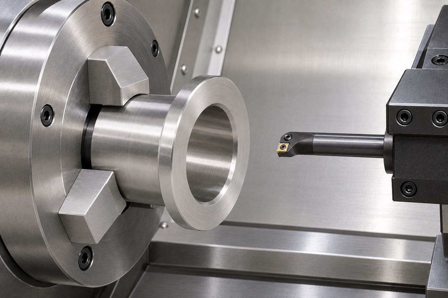
Control the second operation without marking the flange
After parting, use bored soft jaws or a suitable collet on the body rather than gripping the narrow flange rim. Set a clean axial stop and verify that it contacts the designated locating surface. Face the remaining end to the working length, then create the specified bore entry on that end. Use enough support for a stable cut without distorting the sleeve. On the first trial piece, remove and reseat the sleeve to check that the setup repeats. If the length shifts with reseating, inspect the stop, jaw contact and burr condition before changing offsets.
Investigate burrs as a separate failure mode
An exit burr can remain after the length is correct. Inspect both bore entries under consistent light and compare the edge geometry to the drawing. Where the bracket contacts a narrow land, use a controlled tool path or approved manual operation that leaves the specified contact width. Do not chase a visual mark with repeated blending. A smeared edge or rolled lip may also change the fit gauge response. Record whether a defect is on the entry edge, exit edge or working face; that distinction helps the next operator find the originating operation.
Define the first-piece inspection sequence
First verify the free-state working length with a method that reaches the two specified faces. Check bore diameter at accessible depths and angles with a suitable internal gauge. If the drawing requires face runout or perpendicularity, set up a separate check referenced to the stated datum and record how the axis was established. Inspect the flange land after deburring and after any finish process that can change it. Include actual observations and instrument references rather than attaching an empty form. Hold the remaining pieces if a first-piece result calls the route into question.
Use a bench fixture to check the stack
For a trial, a fixture can represent the bracket shoulder and the maximum shaft envelope. Seat the spacer without a tool or extra force and observe whether the bore entry clears the fixture corner. Measure the distance between the defined contacts or check a dedicated limit if that is the agreed decision. This fixture is a mechanical surrogate. The report should identify the represented revision and explain what it did not reproduce, such as hot operation, spray loading or deposits. Any qualification involving the real washer-disinfector remains a separate activity.
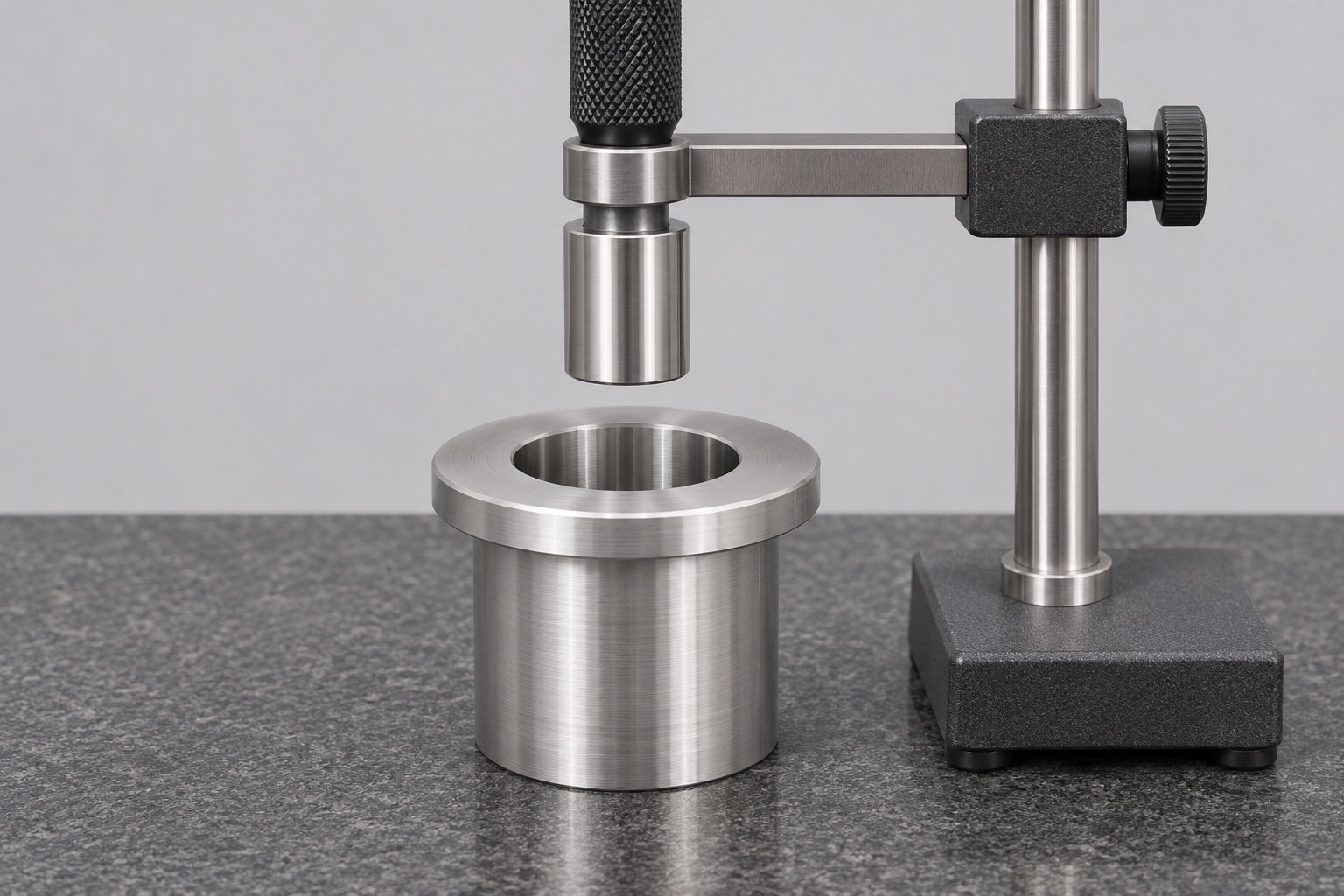
Keep process adjustments tied to evidence
An oversize bore cannot be corrected by changing a turning offset on the completed piece. Segregate it and review the allowed disposition with the drawing owner. If the bore drifts across later pieces, inspect tool wear, chip build-up and gauge condition before assuming the tool needs another offset. If only the axial dimension is unstable, examine the second-setup seating and stop first. The traveler should capture what changed and which pieces were inspected after the change. This is more useful for a repeat order than an unexplained final average.
Agree the handoff from prototype to repeat lot
For the trial order, supply the approved drawing revision, material identification, dimensional evidence and any explicitly requested finish documentation. The next order should refer to that package but must still verify the current drawing. A supplier might change bar source, jaw design or inspection instrument when quantity increases. Identify which changes require approval or renewed first-piece verification. Reserve critical measurements for the drawing features that determine fit and contact. That keeps the repeat plan focused without assuming that a sample machined successfully demonstrates long-term capability.
Identify what the quote does not include
Quote the turning route, edge treatment, inspection and packaging separately where the work content differs. List as open items any finish, cleanliness or traceability requirements the supplied data does not resolve. A change from an as-machined surface to a controlled finish may require new inspection after processing and different handling. The quote for this custom spray arm spacer sleeve should state that it covers the defined mechanical component only. It is not a statement that the part can be fitted to a particular machine or accepted for a validated cycle.
Package with the working surfaces protected
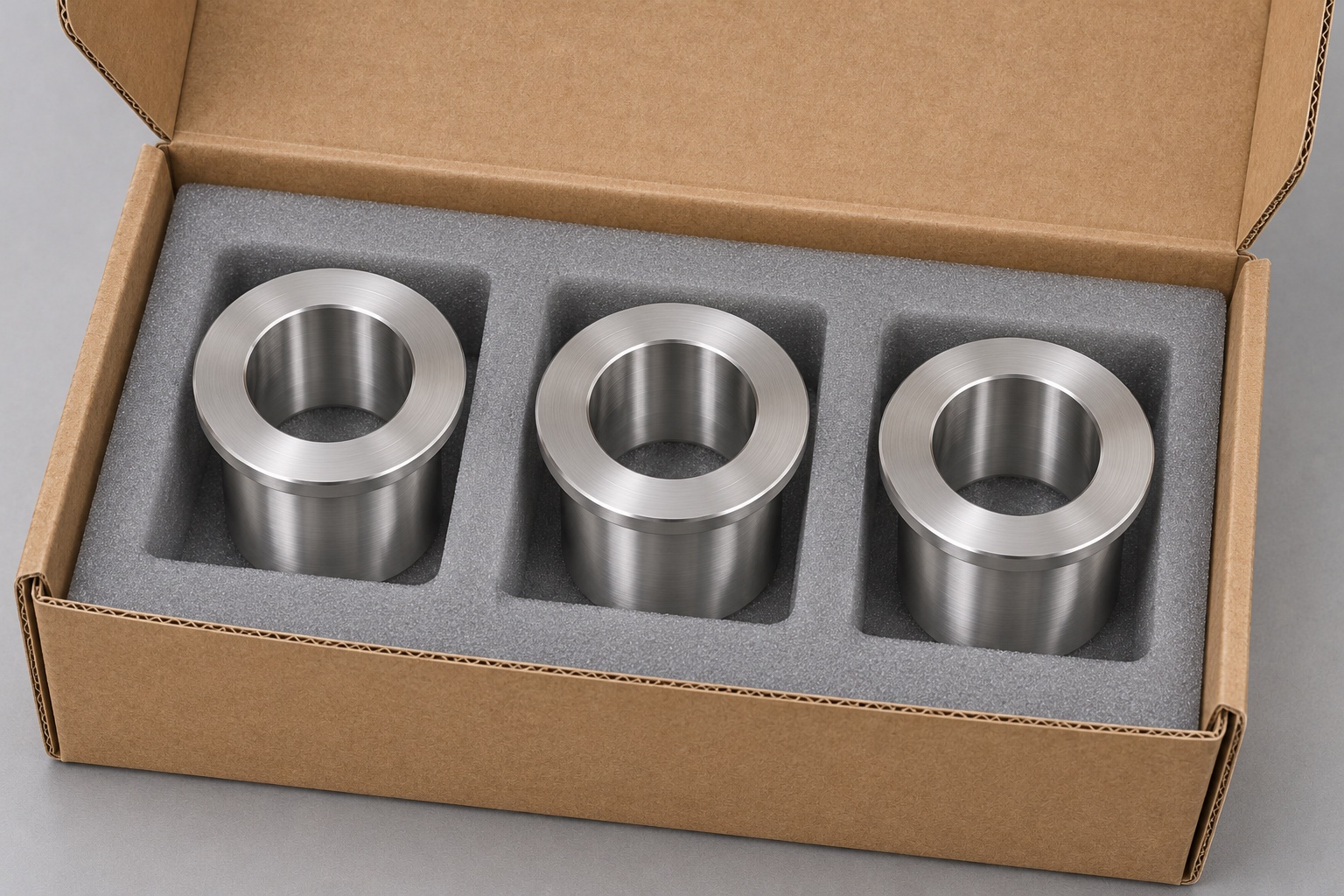
Use a divided protective tray or individual nonabrasive wraps. Do not allow the flange of one part to strike the bore edge of another. Place identifiers on the package, not on a contact surface. Keep the checked first piece distinguishable when the order requires it, while maintaining the same lot reference. At receipt, check the packaging and identity before comparing the measured part to the drawing. The proposed packaging protects dimensions and surface condition in transit; it is not a sterile barrier or proof of a controlled cleanliness level.
FAQ
Why start from round bar rather than a tube?
Round bar is one possible route for a short flanged prototype with a shared spindle reference. Suitable tube can be considered if stock identity, wall allowance and the complete flange envelope are confirmed.
Which dimensions belong on the first-piece report?
Include the working face distance, bore checks and any drawing-controlled face relationship or edge geometry. Record the actual method and condition, including whether the part was measured free or in a specified fixture.
How is the bore checked without confusing it with the chamfer?
Take readings on the cylindrical surface at defined depths away from the entry. Identify the depths and gauge in the report. The chamfer is a separate feature with its own acceptance check.
Does a successful bench fit show washer-disinfector performance?
No. A bench fixture can check seating and mechanical clearance under its own conditions. Cleaning effectiveness and suitability for equipment use require separate evaluation by the responsible equipment owner.
Is the case an example of a shipped customer order?
No. It describes a proposed machining and inspection route for a representative drawing-controlled part, without a claimed customer, delivery record or measured performance result.
What should accompany a request for quotation?
Provide the current drawing, mating envelopes, required quantities, material and finish specification, inspection scope, and the condition expected at receipt. Mark the working surfaces and explain the function of the first-piece sample.

tanghangyun@oemach.com