
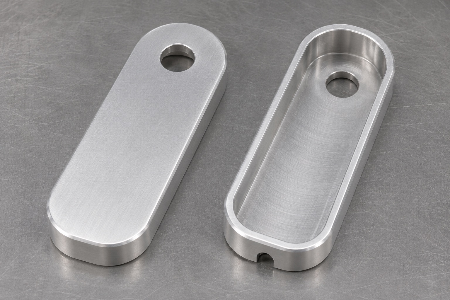
Set the limits of the example
This representative machining case concerns a rounded aluminum housing shell for a hypothetical perimetry response button. It has one front guide bore, a rear cavity with a cover seat and a small cable clearance notch. It is not a customer delivery, certified component or approved replacement. The example proposes a way to review geometry and setup choices before a first article. It includes no electronics, wiring, button force measurements, test results or claims of clinical performance. The equipment owner would provide and approve all mating interfaces and evaluate the finished device separately.

Review the interfaces as a connected set
Start with the released drawing and the actuator, cover and cable envelopes. Identify where the actuator is guided and which surfaces establish the cover plane. Confirm that the bore position is defined relative to a functional reference instead of an unimportant rounded edge. Check that the connector and any specified grommet can pass through the intended assembly path without requiring unapproved material removal. The example assumes these details are known before machining. If one model is provisional, flag the affected checks and do not present an estimated assembly fit as a final acceptance.
Choose stock and plan the release condition
Select the drawing-approved 6061 condition and enough material for the exterior, cavity and setup support. Link the blank to the material record. Review any finishing requirement before deciding on allowance in the bore and around the cover seat. The example does not choose a coating or a numeric allowance without a controlled requirement. A customer-approved finish might require masking and final measurements at specific contacts. State which measurements are in process and which are for release. If stock, finish or fixture changes, reassess the relevant setup and inspection rather than repeating a prior offset without review.
Establish stable machining references
Use the first setup to establish a plane and locating surfaces while the blank is still rigid. Retain gripping stock or use an approved nest that leaves access for roughing. Record the orientation and the intended transfer to the rear or front operation. Avoid using the thin rim as the sole clamping surface once the cavity has been opened. Chips on the support can tilt the part and distort results, so check seating before using a probe reading to set an offset. The approved fixture should reproduce the selected datum relationship without marring final cosmetic surfaces.
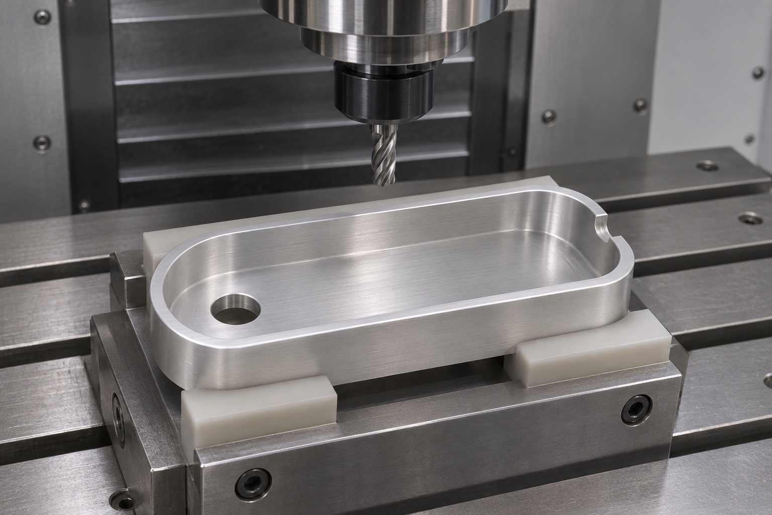
Rough the rear cavity in a supported condition
Remove the main cavity volume in a controlled sequence, leaving allowance for the finish floor and walls. Keep support under the relevant regions and avoid heavy restraint of the thin sections. Inspect the part after releasing the rough setup if movement is a concern. If it shifts, review stock, cutting engagement and fixture support before correcting the program. No measured distortion or capability value is asserted here. The point is to decide when to finish each feature based on the actual condition, rather than assuming a shape held in a vise will remain unchanged after release.
Complete the guide bore and clearance notch
Finish the bore from the approved reference, keeping the required guide length and controlling the exit edge into the cavity. If tool access requires another setup, document how the datum transfers to the new fixture. Finish the notch from the approved cable envelope and inspect it together with the cover boundary. Do not enlarge the notch by default or describe it as a cable restraint. Verify that the relief leaves the required surrounding material. The proposed process separates the bore, cavity and notch checks so a successful fit at one interface cannot obscure a discrepancy at another.
Diagnose a bore that gauges but does not align
Suppose a plug gauge enters the bore, but an inert actuator reference touches one side when located by its mating support. This is a hypothetical scenario. Confirm that the reference and support are correct, then measure the bore axis relative to the functional datums. Check for raised material and a chamfer that reduces the usable guide surface. Do not assume the diameter needs enlargement simply because the reference catches. A fixture or datum-transfer error can produce the same observation. Record contact and measurements separately, and obtain approval before changing the drawing or reworking a sample.
Diagnose an uneven cover seat
Suppose an inert cover rocks on the shell after a final operation. Inspect the named contact segments and look for a local burr or trapped particle. Compare the seat in the accepted support state and check whether fixture pressure changes the result. A warped cover reference can mimic a housing error, so verify the reference before making corrections. Check if the notch or an edge break touches the reference unexpectedly. Do not remove material from the entire seat until the cause is established. The proposed report should distinguish local interference, part form and fixture effects.
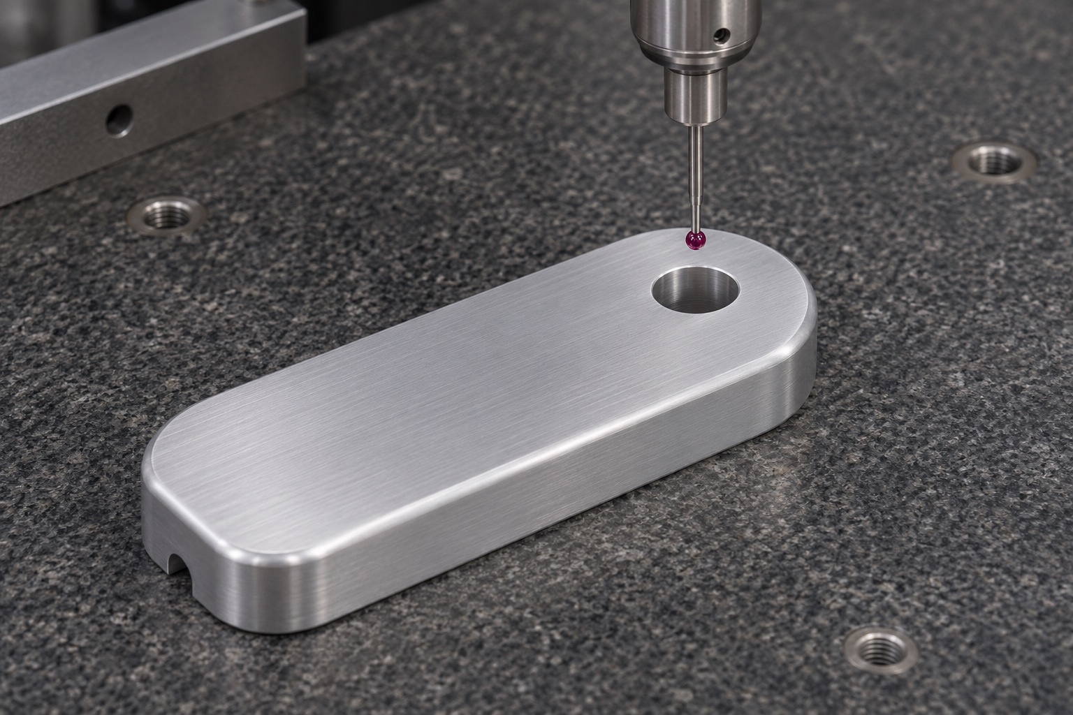
Inspect after finishing and edge work
Check the drawing features in the approved final condition. Measure bore size and position independently, along with cavity depth, seating form and notch profile. Inspect bore exit, notch and cover edge for raised material. If finish treatment is specified, verify critical surfaces after it and record masking boundaries. Use accessible measurement equipment and identify the supporting fixture. An inert envelope check may help locate contact, but it does not replace feature measurements. Apply the agreed decision rule near a tolerance boundary. This example supplies no numerical results or guarantee of measured process capability.
Use a bounded mechanical check
An approved inert actuator and cover envelope can be placed on the bare shell to examine access and contact. Document the reference revision and orientation. Do not energize an assembly or use a clinical instrument for this check. A fit observation applies only to the specified geometry and state. It does not verify electrical safety, response timing, actuation force, cable life or any diagnostic outcome. Report interference without forcing or modifying the reference. If a design change is proposed, return the issue to the responsible owner before repeat machining or claims of system compatibility.
Protect the housing during delivery
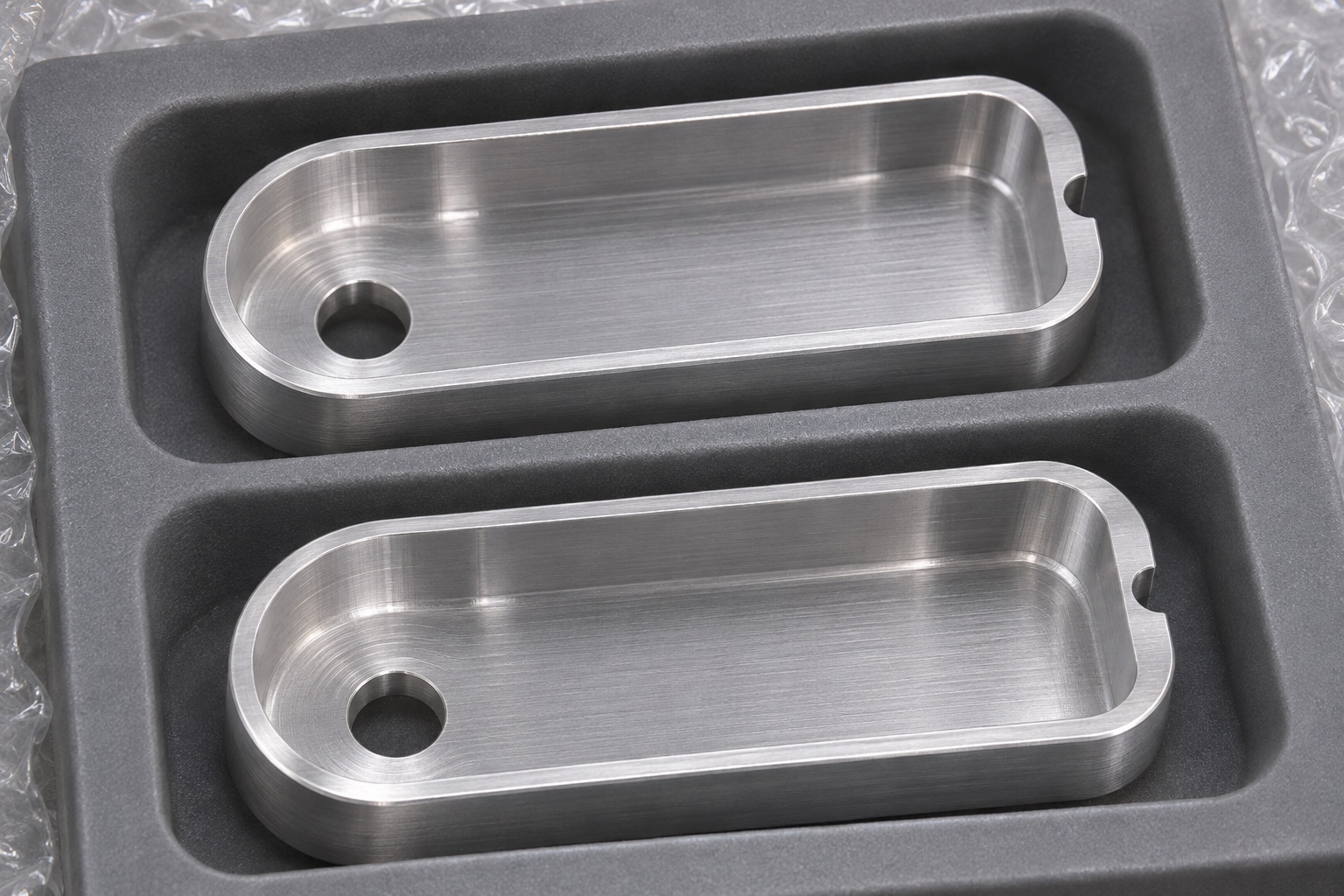
Remove machining residues using the agreed process and inspect the cavity, bore and notch. Use separate tray pockets that support the shell without squeezing its thin walls. Keep the cover seat and exterior away from abrasive contact, and prevent labels or adhesive from reaching functional surfaces. Check that parts cannot touch one another under normal handling of the proposed package. Record revision and lot information when requested. This description is protective component packaging, not a validated sterile or medical transport system. Any additional cleanliness requirement must have defined acceptance and separate evidence.
Close the first-article review with evidence
The proposed handover combines the controlled revision, material record, setup and finish notes, feature measurements and packaging details. Include inert fit observations only when they were actually performed with an approved reference. If a first article reveals a conflict between the actuator guide and rear support, clarify the design before producing a repeat batch. No real customer, delivered quantity, device qualification or clinical outcome is presented. The case demonstrates how to define a machining decision without implying approval of a finished response device. The responsible equipment owner retains the system-level release decision.
FAQ
Is this a replacement for a named perimeter?
No. It is a representative machining example. Compatibility and intended use would require approved interfaces and independent equipment-owner evaluation.
What if the plug gauge passes but the actuator rubs?
Check the reference and datum setup, then evaluate bore position, usable guide length and local edges. A size check alone cannot resolve an alignment problem.
Why rough the cavity before final inspection?
Material removal can affect released geometry. Roughing and reassessment help establish a stable finish plan without accepting measurements taken only under cutting restraint.
Can a cover fit show electrical compliance?
No. It only describes mechanical contact under defined conditions. Electrical and equipment performance remain outside the machining report.
What should the cable opening be checked against?
Use the approved cable and cover envelope with the required entry direction and edge condition. The notch is not a verified strain relief.
What should be protected in the tray?
Protect the cover seat, bore and cosmetic faces, and avoid load on thin edges. Separate housings and preserve the agreed lot identification.

tanghangyun@oemach.com