
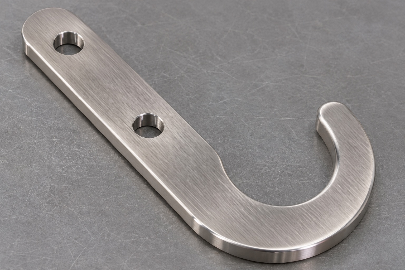
Define the representative job
This is a representative machining example, not a customer delivery or an approved endoscope support. The assumed component is a flat J-shaped 316L plate with two through holes along its shank and a rounded open hook. An approved cabinet interface and an inert carrier envelope would define the mechanical requirements. The objective is a repeatable machining route and a reviewable record of geometry, not a claim about drying, safe load or device compatibility. No measured data, certifications, shipment quantities or real instrument fit results are presented. The design owner would approve all functional dimensions before a sample is made.

Review the hole-to-profile relationship
The proposed drawing identifies a seating face and a locating reference tied to the mounting pattern. Before choosing a fixture, confirm whether the holes locate or simply provide clearance. Compare the profile to a section of the approved mating carrier. The visible open area is not the only important feature; the shank transition and tip can affect entry. Ask the buyer to identify permissible contact and required clearance through the intended path. If the rail drawing and carrier model use different revisions, record the discrepancy and hold the fit decision until the design owner resolves it.
Choose and identify the blank
Start with a drawing-approved stainless plate or a near-net blank with enough allowance around the profile. Match the blank to the material record before it is separated from the stock. Consider whether the incoming faces can remain or must be machined to establish thickness and flatness. A near-net process may leave an edge that requires additional stock removal; do not assume it is an accepted finish. Record the incoming condition and the intended finish sequence. The representative route does not prescribe a universal stock thickness or tool setting because the controlled design and actual equipment determine those choices.
Establish the first reference in a stable setup
Support the rough plate across its broad surface and locate it with stops that do not obstruct drilling. Establish the mounting plane and accessible reference surfaces where the drawing requires machining. Produce the holes from the approved datum arrangement. Confirm the backing surface prevents exit damage and leaves room for the drill. A clean support is important because a trapped chip can make a flat-looking blank sit at an angle. Record which surfaces the next fixture will use, and inspect those surfaces before transfer. Do not use the visible outside edge as a substitute for a controlled mounting reference.
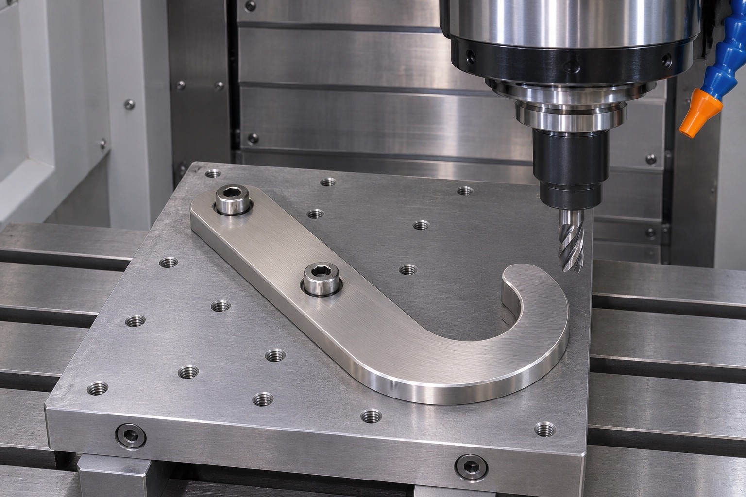
Transfer to a perimeter fixture
In the proposed second setup, a backing plate supports the work while the curved boundary remains accessible. An approved hole and a second locating contact can orient the plate without forcing an overconstrained fit. Use separate retention where needed and confirm clamp clearance before running the profile. Check that the hook region stays supported as rough stock is removed. The fixture should not mark the finished mating plane or move when the last section is cut. Record the setup conditions so a later operator can reproduce the support instead of compensating for a different seat with an offset.
Finish the throat and tip
Rough the outside and inside shapes, leaving a controlled allowance. Complete the throat with a tool that reaches the concave region at a reasonable extension and maintains a stable cutting path. Check the transition from the curve to the shank and the rounded tip separately. A mark left by an entry move is not necessarily located where a later gauge will reveal it. Plan tool entry and exit outside the most sensitive contact region where practical. Then release the plate and assess whether the final profile or face moved. This route proposes process checks without promising an unmeasured capability.
Diagnose an obstruction at entry
Suppose an inert carrier reference stops at the mouth while the main seating radius measures within its requirement. This is a hypothetical scenario. Check orientation, the tip and the local opening before changing the entire contour. A burr or chamfer crossing the entry path can create contact that a radius measurement farther inside cannot detect. Compare the gauge geometry with the drawing and check that the support reproduces the approved rail position. If a revision mismatch is found, report it rather than trimming a sample to make it pass. Any approved correction must be followed by targeted reinspection.
Diagnose an offset after mounting
Suppose the profile appears centered when measured from the blank edge but shifts when assembled to an approved reference plate. Check the relationship between the mounting feature and throat in the functional datum scheme. A reference chosen for machining convenience can differ from the true locating feature. Verify the hole position and whether fastener clearance permits movement. If the setup uses two pins, verify that they do not force the part into an artificial position. Document the observed discrepancy and investigate the fixture, part and reference separately. An apparent shift is not evidence of any specific cause until these checks agree.
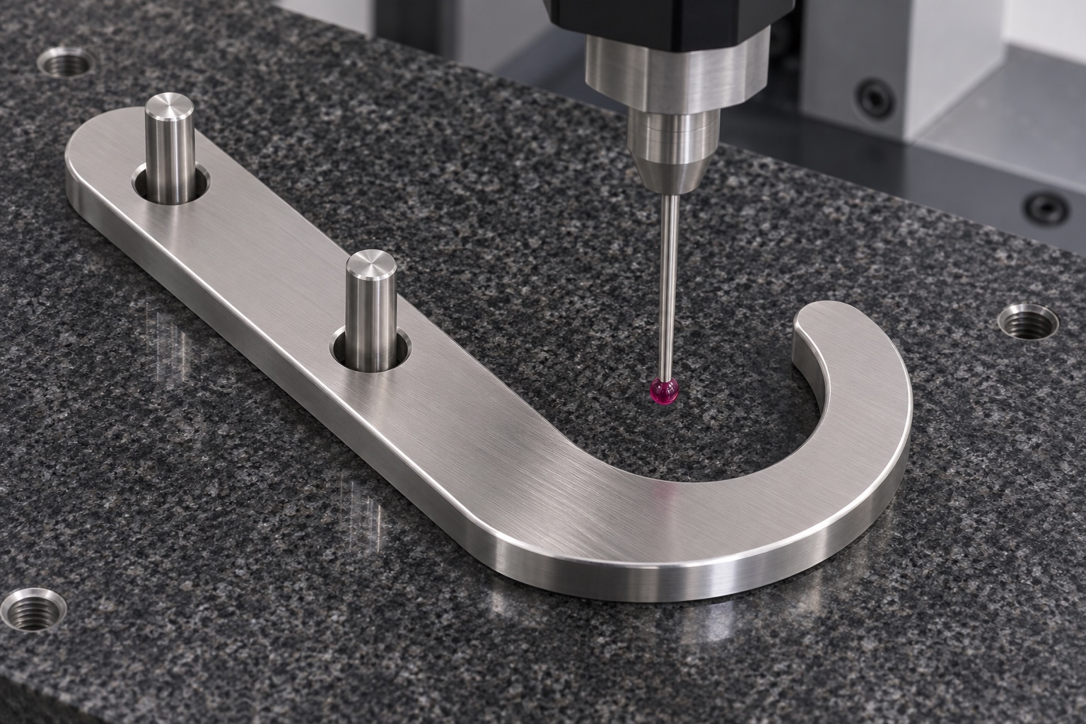
Inspect after controlled edge work
Apply the specified edge treatment at the tip, throat, outside contour and hole exits without altering the seating plane or minimum section. Use the drawing's limits rather than a general polished appearance. Then inspect the plate thickness, face condition, hole pattern and profile at the required sections. Note the equipment, alignment and support state. If the drawing calls for a finish operation, include a check in the final condition after that operation. An inert fit observation supplements, but does not replace, the numerical report. Near-limit readings should be handled with the agreed acceptance rule rather than rounded into compliance.
Define residue checks and protective packing
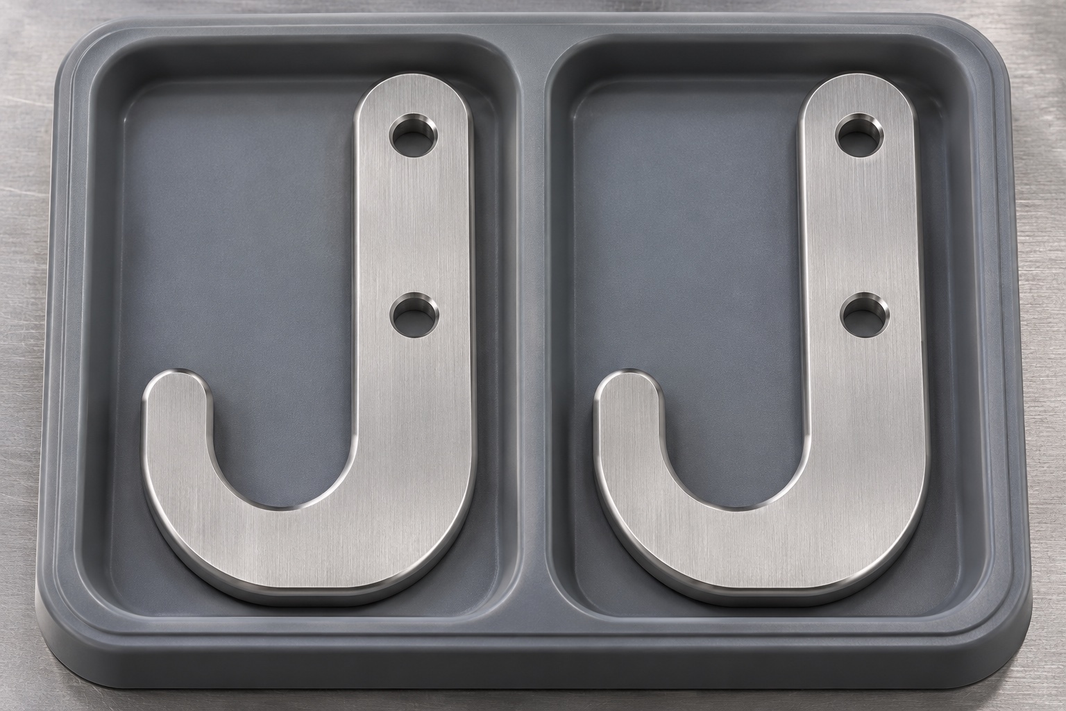
The proposed cleaning step would remove machining debris and agreed residues before final handling. Inspect the curved seat and hole exits where particles or burrs can remain. Place the plates in separate compartments so the hook tips do not touch another part or bear against the cover. Verify retention without forcing the profile into a tight pocket. Identify the lot and revision on the package where required, keeping adhesive away from functional faces. The example offers no sterile barrier, transport qualification or cabinet-cleaning claim. Any such requirement must be defined and demonstrated separately.
Review first-article evidence with a defined gauge
Use a controlled mounting reference and an inert carrier envelope to document entry, seating and removal. Capture the reference revision, orientation and observations without testing an operating cabinet or a clinical instrument. Record exactly where a contact occurs and whether it is intended. A sample that seats under extra force is not equivalent to meeting a drawing requirement. A conforming bench result would apply only to the tested arrangement. The responsible owner must separately assess attachment strength, stability, service conditions and compatibility. That boundary should be visible on the inspection and handover records.
Hand over the process and its open issues
The proposed package includes the approved revision, material traceability, route and setup notes, final-condition inspection and packing description. Document a dry fit observation only if it was actually performed against an agreed reference. If the first article reveals an ambiguous contact or a fixture that masks part movement, resolve it before repeat machining. Do not present a proposed process as a qualified production result. This example shows how to separate drawing conformance from system validation and how to ask for evidence at each gate. It does not represent an installed product, a measured load test or a named customer.
FAQ
Is this an approved replacement hook?
No. It is a representative manufacturing example. A named cabinet, carrier and mounting arrangement would need approved drawings and independent device-owner evaluation.
Why establish mounting references before profiling?
The references relate the throat to its installed position. A perimeter machined accurately from an unrelated blank edge may still be offset after mounting.
What if the gauge stops at the hook mouth?
Check the local opening, tip, burrs and insertion orientation. Confirm the gauge revision and support before changing any approved geometry.
Should the plate be inspected while tightly clamped?
Only if that restraint is the documented inspection condition. Check released form where specified so fixture pressure does not mask movement.
Does a dry fit check verify load capacity?
No. It evaluates geometry in a specific setup. Load, retention and service suitability require separately defined evidence from the responsible design authority.
What belongs in the first-article package?
Provide material identity, drawing revision, setup and measurement evidence, and the agreed cleaning and packing scope. State the limitations of any bench fit observations.

tanghangyun@oemach.com