
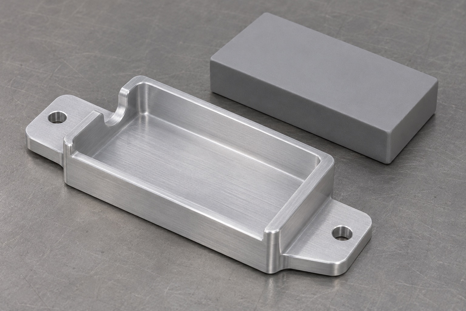
The example and its limits
This is a representative machining example for an exterior medical refrigerator logger saddle, not a customer delivery or an approved replacement component. The assumed geometry is a rectangular pocket with low walls, a cable clearance relief and two mounting ears. A drawing and inert housing model would define fit. The job would not include probes, wiring, temperature calibration or changes to refrigerator hardware. No certified status, measured temperature performance, actual installation or shipment quantity is implied. The purpose is to show how a buyer could evaluate a machining plan and separate component acceptance from the instrument owner's system validation.

Review the drawing and two interfaces
Before quoting, identify the reference mounting plane, the pocket floor and the faces that locate the inert housing. Request the approved attachment pattern and connector envelope rather than estimating them from an image. In this example the external mounting interface would be reproduced by a bench plate supplied or approved by the equipment owner. The plate is a mechanical reference and does not reproduce refrigerator operation. Compare the revision of the plate with the part drawing. If the attachment model omits a washer, tool path or panel obstruction, mark it as an unresolved interface condition and pause that portion of the fit decision.
Select blank stock and the finish sequence
Use only the approved 6061 stock condition and track material identity from the blank to the final report. Check that the blank leaves enough allowance for the ears and pocket while retaining useful gripping surfaces. If anodizing or another finish is specified, review masking and final dimensions before programming. No finish is assumed merely because the part is near medical equipment. The process plan should say which surfaces are checked before treatment and which are accepted afterward. A material or treatment change requires approval; it cannot be justified only by the appearance of a sample or by a successful dry fit.
Establish a stable primary setup
Create the initial reference plane and accessible outer surfaces while the blank still has adequate support. Use a fixture that allows the chosen tool paths without forcing thin areas against the jaws. Select locating stops so chips cannot easily collect beneath the reference. Mark how the blank is oriented through transfer, but avoid marking the final seat. In the proposed sequence, some rough stock remains on the walls while the pocket is opened. Confirm clearances for tool approach and tool exit before cutting mounting features. If a revised blank moves the gripping surface, review the setup and probe access instead of copying prior offsets unchanged.
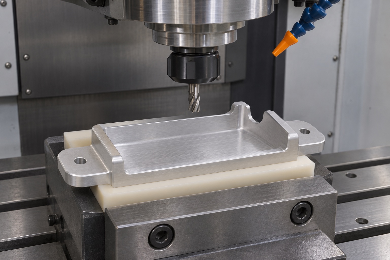
Rough the pocket before finish sizing
Remove the main pocket volume in stages appropriate to the stock and tooling. Keep the floor supported and leave a deliberate allowance on walls and contact surfaces. After roughing, assess whether the part moves on release. If it does, check blank condition and workholding before selecting a new finish strategy. This example does not present a measured deflection or guarantee a capability value. The proposed route is intended to prevent distortion from being hidden in a fixture. Final milling should reference the approved geometry and produce the specified floor and corner radii without relying on force to match a gauge.
Complete the mounting ears and relief
Finish the hole pattern relative to the functional mounting references. Check head and tool access against the approved envelope without assuming that larger holes will solve assembly problems. Mill the cable relief and inspect the transition at the lower wall, where an edge can be difficult to see. The route keeps the relief separate from the locating surfaces so edge correction does not unnecessarily change seating. If the connector shape is still provisional, do not claim fit on the basis of the body model alone. Record which geometry is final, which is a placeholder and which must be approved before production release.
Diagnose a housing that rocks in the pocket
Suppose an inert housing gauge touches two corners and rocks, even though pocket width is within the agreed tolerance. This is a hypothetical condition. Check the housing corner envelope against the internal radii and confirm that the gauge is seated in its intended orientation. Look for a burr or fixture particle under the base. Compare the actual contact regions and floor readings before deepening the entire pocket. If the corners cause interference, discuss a local approved relief with the drawing owner. Record the revision and repeat checks on affected features after correction rather than presenting a forced fit as acceptance.
Diagnose an accessible hole but blocked connector
Suppose the mounting screws are accessible with the housing removed but the connector envelope conflicts once the gauge is seated. First check the required connection sequence and the model revision. Identify whether the collision is with the relief wall, the fastener head or the available tool path. Enlarging one notch may not solve a conflict elsewhere, and it can weaken or remove an intended contact edge. This case proposes recording the interference location and returning it to the responsible design team. No operating cable is bent or installed in a refrigerator during the check. A mechanical clearance observation does not verify electrical or temperature performance.
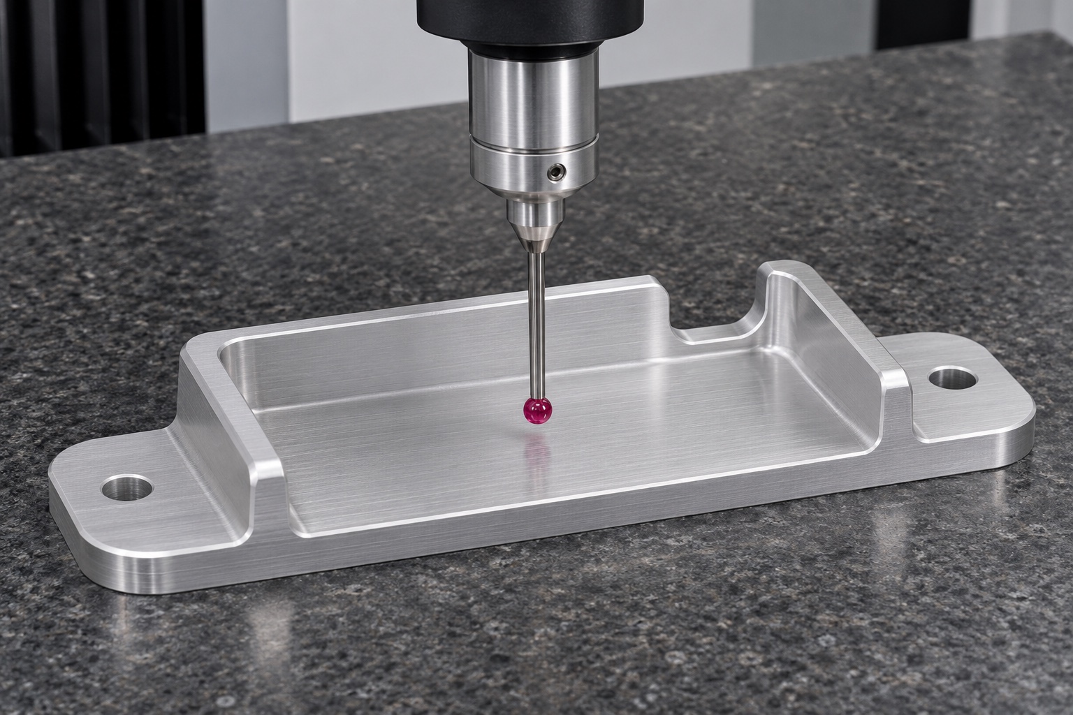
Inspect after all required processing
The proposed report covers the mounting plane, hole pattern, pocket dimensions, corner profile, floor position and relief shape. Measure critical features in the agreed final condition after any specified finishing. Confirm that the stylus reaches the appropriate wall region and does not mistake a corner radius for a straight surface. Record the support condition and measurement locations. If a limit is close, use the agreed decision rule and consider setup repeatability. List bench fit observations separately from dimensional data. No actual inspection values are supplied here; the design team would agree which characteristics and supporting records are necessary before making a first article.
Clean and protect the relevant surfaces
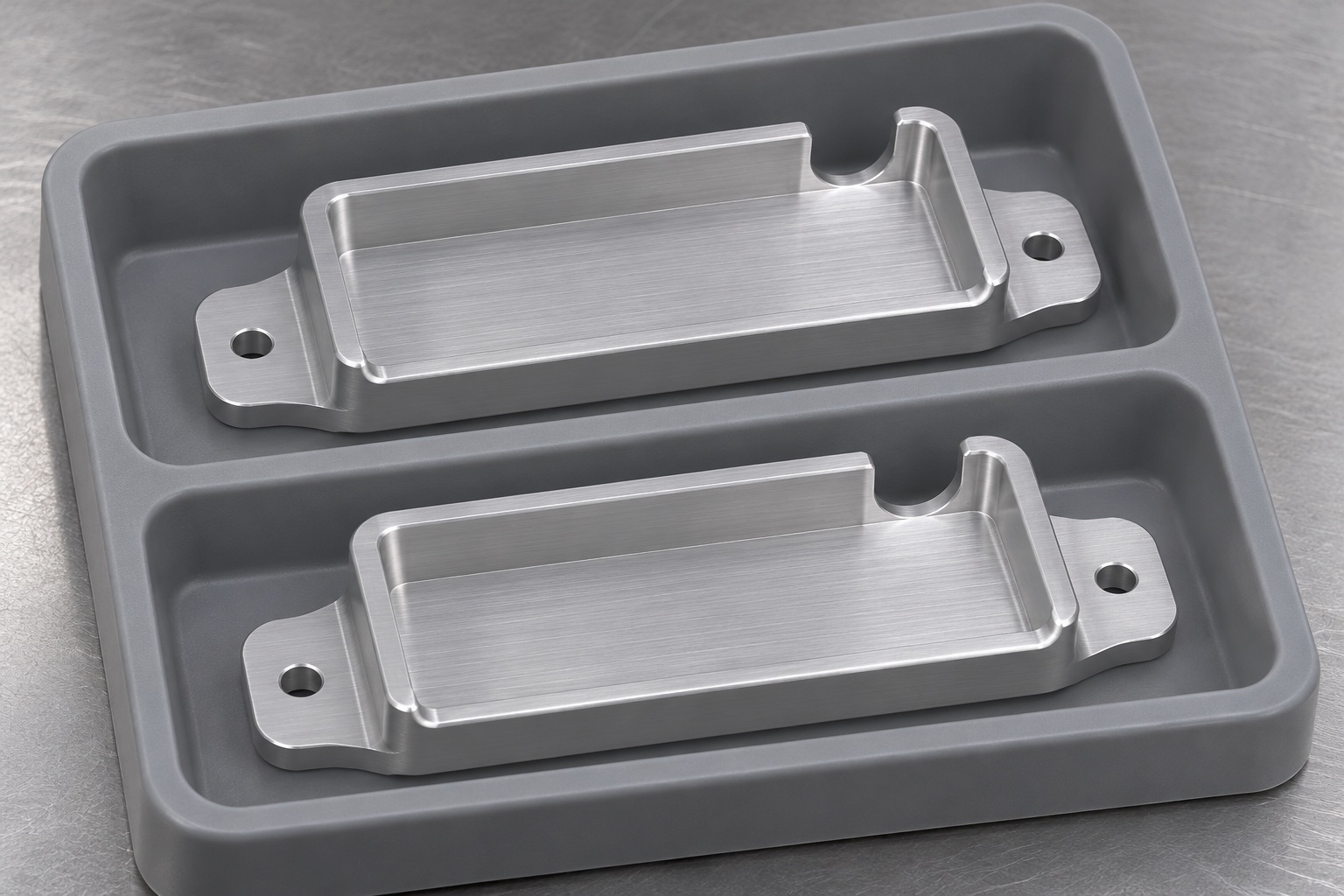
Inspect the relief, floor and hole exits for chips and raised edges after the approved cleaning step. Avoid dragging parts across one another while transferring to the packing area. Provide separate pockets that support broad surfaces without pushing on wall tops or the cable relief. Confirm that separators do not mar the agreed finish. Mark the package with the part revision and lot references where required, keeping labels off the seating surfaces. The example describes protective packaging only and claims neither sterile status nor a validated cleanliness level. Any extra cleaning, packaging or transport qualification must be specified and supported by separate evidence.
Define a bounded bench acceptance check
With the agreed interface plate and inert housing gauge, document the seating and clearance sequence. Check the attachment envelope without modifying a refrigerator or an actual logger. Record whether any contact is intentional and whether the gauge can be removed as specified. If the fit changes after reseating, inspect the fixture for debris and repeat the setup before concluding that the part needs adjustment. Keep the bench check attached to its drawing and fixture revisions. A pass would apply only to this defined geometry and support condition. It would not authorize an installed system or establish that monitoring remains valid in use.
Prepare the handover for the next decision
The proposed handover includes revision-controlled design inputs, material traceability, process and finish notes, feature-level results and packing evidence. Add photographs of the agreed bench arrangement if the buyer requests them, with a clear distinction between illustrative images and measured evidence. If interface information remains incomplete, label the open issue instead of claiming that the design has been validated. The device owner decides whether and how to proceed with equipment installation and performance qualification. This case offers a possible CNC route and acceptance framework, not a fabricated successful project, product certification or assurance of reliable cold-chain operation.
FAQ
Is this an actual refrigerator installation?
No. It is a representative CNC machining example. It includes no customer delivery, instrument approval or reported temperature results.
Why leave allowance during pocket roughing?
Allowance lets the shop assess shape after material removal and clamping release before committing to final dimensions. The actual route depends on the approved stock and drawing.
What is checked if a housing rocks?
Compare the corner envelope, seat and raised edges, and inspect the fixture for debris. Do not deepen or widen the pocket before identifying the contact.
Can a mounting plate test validate probe readings?
No. It only represents a mechanical interface. Sensor placement, calibration and temperature behavior are separate equipment-owner decisions.
Does finish affect clearance?
It can affect final pocket or hole geometry. Specify the accepted final condition, masking if required and the features that are checked after treatment.
What should the packaging protect?
Separate parts and prevent rubbing on the pocket, mounting pads and cable relief. Maintain revision and lot identification without placing adhesive on functional surfaces.

tanghangyun@oemach.com