
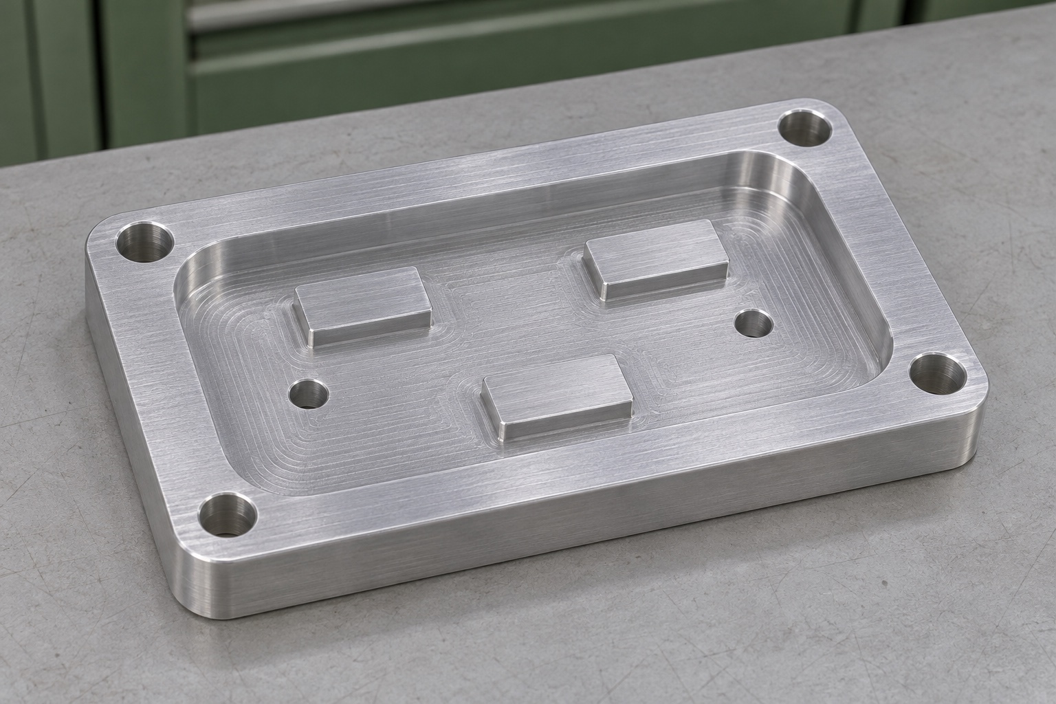
Representative machining scope
This 6061 intraoral scanner target carrier is a representative CNC milling example for discussing a component used in a dental equipment engineering fixture. It is not a delivered customer part, a calibrated artifact or an approved accessory for a named scanner. The case examines a mounting base, target seating regions and locating features through a proposed manufacturing and inspection route. No customer, certification, measured production result or optical performance is claimed. The target itself and the scanning system remain outside the component example. Their requirements and approval evidence cannot be supplied by a carrier photograph or by an unloaded seating observation.

Generic layout under review
The holder is considered as a compact aluminum plate with a shallow target pocket, defined support lands and locations for separately specified locating features. Mounting holes attach the carrier to an engineering fixture. The actual drawing must resolve the seating contacts, clearances and locating interfaces; the images are not an authoritative dimensional model. A pocket floor and a raised land are not automatically equivalent reference surfaces. The manufacturing question is how to preserve the intended target plane and locator relationship to the mounting base. This gives the example a specific inspection purpose without suggesting a calibration method for a commercial dental scanner.
Information needed for quotation
The design package would provide the controlled model and drawing, alloy and temper, stock form, quantity, final finish requirements and inspection deliverables. It would identify which surfaces seat the target and which merely provide clearance. Separate locators or hardware need their own interface and installation requirements. If the owner requires an assembled reference-height check, that must be specified rather than inferred from a component picture. The example does not choose a target standard or establish optical acceptance criteria. Those decisions belong to the responsible system designer and must be supplied before a real manufacturing package can be considered complete.
Material identity and final process state
The proposed route begins with traceable 6061 stock in the required condition. Identification follows the blank through cutting, machining, finishing and packaging. The plan records any later treatment that can affect seating or locating features, including the final state in which dimensions apply. A material or finish substitution requires review instead of being justified by similar appearance. No coating, certification or qualified production route is claimed here. The case describes the records that an actual order would need and the questions that should be settled before a supplier promises a finished carrier suitable for the owner's specified dimensional acceptance.
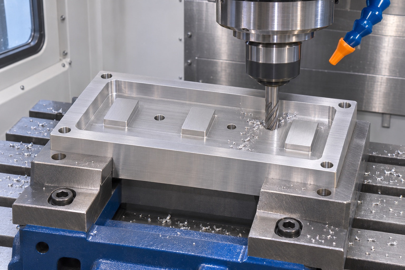
Establishing the mounting reference
A first machining stage would prepare or qualify the mounting face and the reference features needed by subsequent operations. The setup identifies support and clamp contacts so the same datum structure can be recovered after transfer. The plan should not force an inspector to choose a different convenient edge when the part is turned over. If a shallow pocket is rough-machined at this stage, preserve sufficient support and finishing allowance for the functional lands. The exact sequence depends on the released geometry. The important point is that the mounting reference remains defined through the route rather than being recreated independently at every operation.
Milling the target seat and clearances
The next proposed stage distinguishes the lands that support the target from relief and clearance surfaces around them. Cutter access near pocket corners and narrow raised regions needs review before the route is accepted. The fixture must not bend the carrier into an apparently correct plane during finishing. If support or geometry changes after roughing, the finishing plan should account for that change. This case does not claim an achieved flatness or surface roughness. The actual drawing must define the characteristic, and the inspection method must be able to evaluate the relevant regions after the specified process and support condition.
Producing locating and fastening features
The route treats locating features separately from holes that merely fasten the carrier to its support. Their size, position and relationship to the seating regions may have different requirements. Where practical, related features would be finished while preserving a common reference. If repositioning is needed, the setup sheet identifies how that reference is recovered. A pin entering a hole is not enough to establish the hole's position. Separate hardware is not installed on the basis of an image: the real order must identify its specification, installation method and any required final assembly inspection.
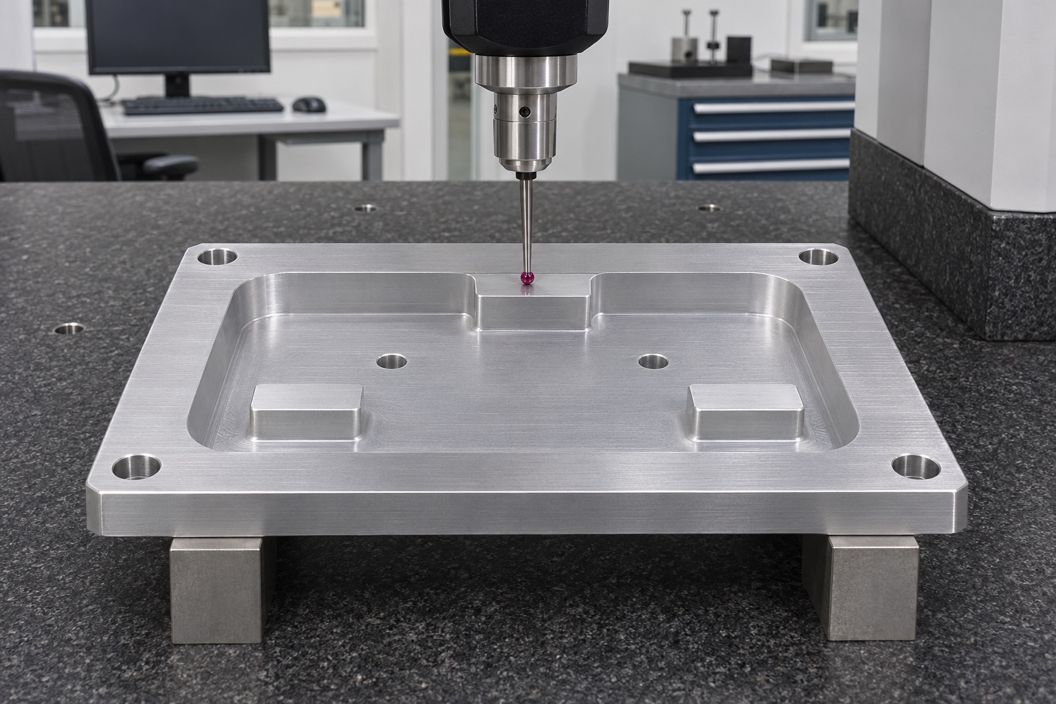
Proposed first-article inspection
The inspection list would include the mounting reference, specified seating lands, locator positions and any required installed reference-height relationship. It would identify the evaluated regions, measurement method and support state. A coordinate or other appropriate dimensional method could be considered according to access and the actual characteristic. The report should not fit a convenient plane through unrelated pocket regions and describe it as the target seat. No measured results are supplied in this representative case. A real record would connect the observations to part identity, drawing revision, material requirement and the final condition after any specified treatment or assembly operation.
Inert reference seating observation
After dimensional inspection, a separate engineering fixture could use an identified inert blank to observe seating and clearance. The procedure would record the blank, support and observation positions. No optical calibration is performed and no operating clinical scanner is modified. A blank that sits without rocking may help reveal a local geometric issue under that arrangement, but it does not establish scanner accuracy, repeatability or compatibility. Keeping this observation separate from the component measurements makes the evidence more useful: it shows exactly what was compared without giving a local bench trial the authority of an approved calibration or system validation.
A possible seating finding
Consider an observation in which the inert blank touches a clearance region before reaching the intended support lands. The next review would inspect local edges, land heights, locator condition, reference-object identity and fixture support. It would preserve the contact location before choosing an action. Lowering the entire seat or opening the pocket automatically could change the intended reference plane without addressing the cause. This scenario is a decision example, not a claim that a production failure occurred. Approved rework would require reinspection of affected features and repeat observation under the same identified conditions, with any design change controlled by revision.
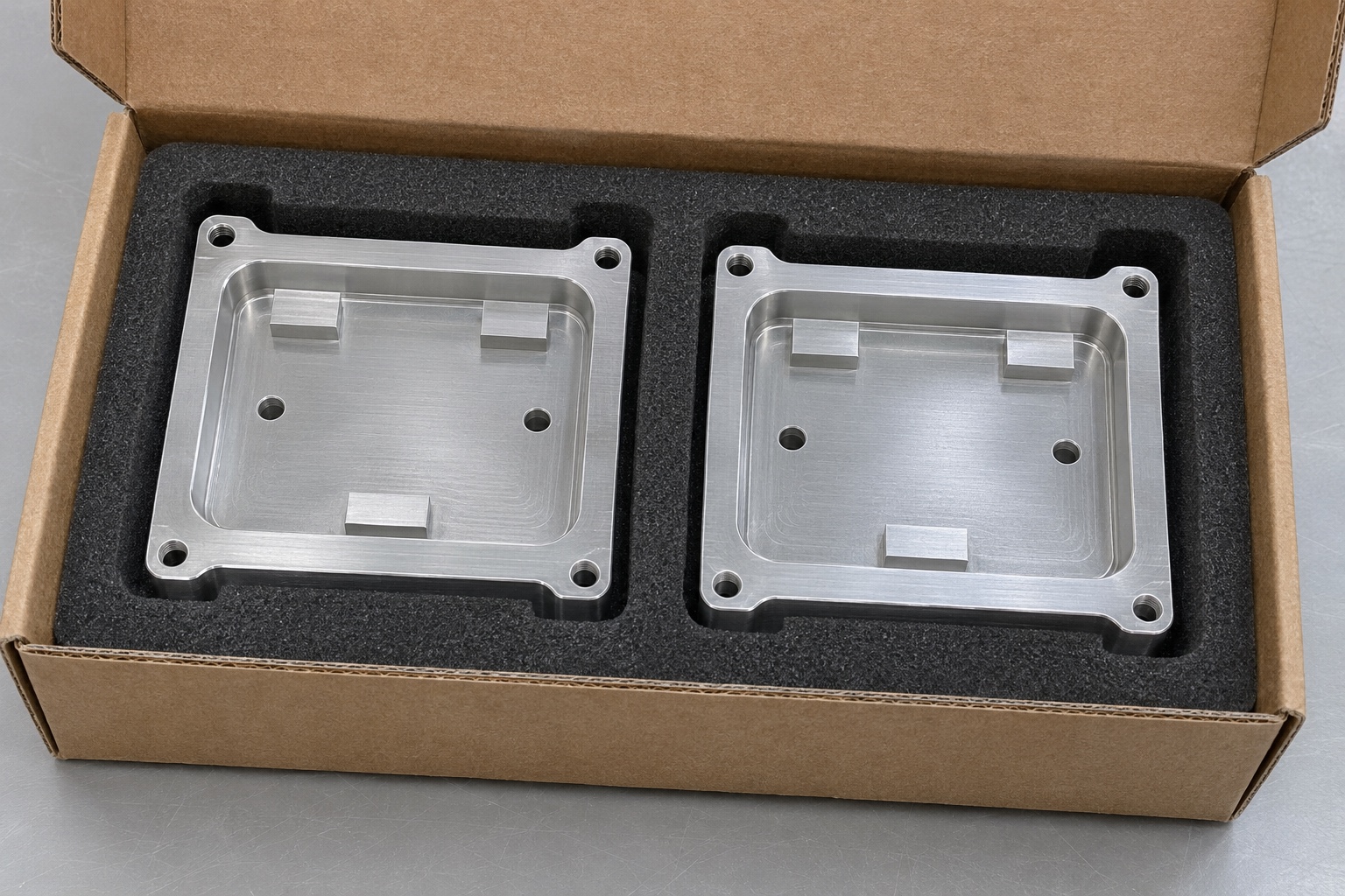
Protection and identification
The packaging proposal supports robust regions and keeps seating lands and locating interfaces away from contact damage. It avoids packing forces or inserts that distort the carrier or leave an unapproved film on a functional surface. Identification remains connected to the material, finish and inspection records without an uncontrolled mark on the target seat. Ordinary protective packaging is not a sterile barrier or an optical qualification. If a specific cleanliness requirement applies, it must be defined with acceptance evidence. The receiving team should be able to retrieve the correct revision and repeat dimensional inspection without discovering that the reference surfaces were altered in transit.
From example to manufacturing request
A real order should add the final model and drawing, material condition, quantity, finish requirements and inspection scope. Highlight the actual mounting datum, support lands and locator interfaces. Resolve whether separate hardware is included and whether final-state or assembled measurements are required. Discuss any difficult tool or measurement access before assigning a critical characteristic that cannot be verified. Agree how first-article findings and proposed corrections will be handled before production continues. The representative case provides a route for that discussion; it does not replace a released component design, actual measurement results, a calibrated reference artifact or approval of the complete scanning system.
FAQ
Is this a delivered dental scanner accessory?
No. It is a representative machining example without customer delivery data, commercial compatibility or optical performance claims.
Does the carrier replace a calibration target?
No. The holder and the separately defined target have different roles. Machined seating geometry does not provide the target's calibration information.
Can a pocket floor be accepted as the seating plane?
Only if the drawing defines it as such. This example distinguishes actual support lands from clearance regions and requires the intended references to be explicit.
What must be defined for separate locating pins?
The real order must identify their specification, interface, installation condition and any final inspection required. Their dimensions cannot be selected from a photograph.
Does a stable inert blank prove scanner repeatability?
No. It is a limited geometric observation in one setup. Optical repeatability and system approval require separate controlled evaluation.
What evidence would accompany a real first article?
The agreed drawing controls the deliverables. They would identify the part, revision, material, final state and the measured seating and locator characteristics, with separate bench observations where required.

tanghangyun@oemach.com