
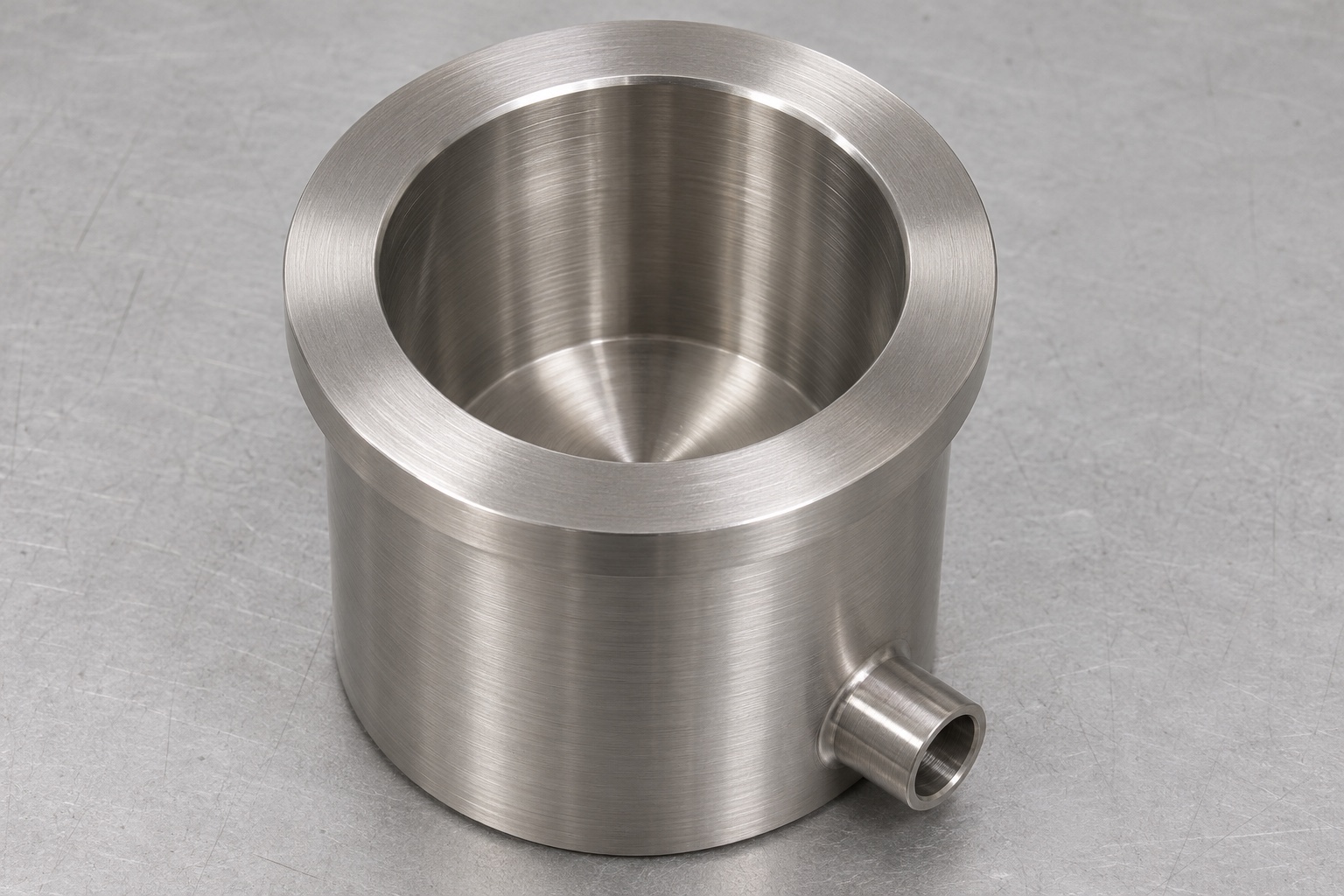
Representative case and its boundaries
This 316L analyzer probe wash cup is a representative CNC machining example, not a report of a customer delivery. It examines how a turned cavity, mounting reference and radial drain can be defined and inspected as one component. No customer, certification, measured production result or clinical performance is claimed. The proposed route is intended for engineering discussion before a drawing is released. It does not establish wash effectiveness, compatibility with an analyzer, or readiness for contact with samples or reagents. Those questions belong to the device owner's approved design and validation work rather than to an image or a machining description.

Component layout selected for review
The part considered here is a short stainless cylinder with a central cavity, an annular upper rim, a locating exterior surface and one drain connection near the lower region. These features create different manufacturing questions. The cavity needs accessible cutting and measurement, the rim provides an axial reference, and the drain creates an internal intersection. A drawing must resolve the actual connection construction and cavity floor shape; the images do not prescribe them. Keeping this layout generic avoids implying that a photograph is a replacement-part drawing. It also makes the review focus on the machining relationships that a supplier can control.
Inputs required before quotation
The starting package would include a controlled three-dimensional model and a drawing defining the material, critical dimensions, datums, finish and edge conditions. A quantity and inspection scope are also needed. If there is a downstream treatment, state whether dimensions apply before or after it. The supplier should identify unresolved drain access or measurement questions instead of filling them with shop assumptions. A quote for a representative geometry is not authorization to manufacture a component for an operating instrument. Review the final revision and application requirements before any purchase order is treated as a production release.
Material and stock planning
The example calls for identified 316L stock rather than an unspecified stainless blank. The stock size should leave suitable workholding and machining allowance without forcing an unnecessarily long tool reach. Material documentation, when required, must remain traceable to the batch through cutting and subsequent operations. A material substitution would need approval even if the proposed alternative appears easier to machine. The manufacturing plan should list the stock condition and later finishing steps so dimensional inspection can occur at the correct stage. This case does not infer any certification or application suitability solely from the choice of alloy.
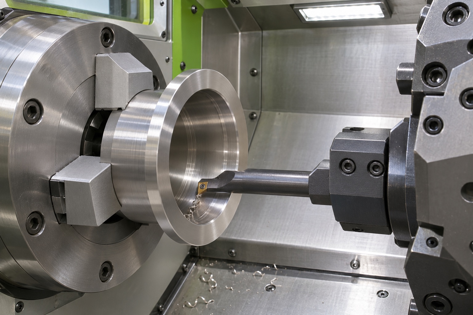
First operation on the turning center
A proposed first operation establishes the face, cavity and related exterior locating surfaces in a controlled setup. The drawing relationships determine which features benefit from being finished together. Roughing should leave a manageable finish allowance and avoid creating a thin unsupported condition too early. Before cutting, confirm that the boring tool can reach the cavity floor and evacuate chips without damaging the rim. No universal feed, speed or tolerance is offered here: the actual tooling, stock and geometry determine the qualified process. The intended output is a stable reference for the next operation, not an asserted finished production result.
Transfer and drain machining
The next setup locates on the approved turned references while keeping clamping pressure away from vulnerable cavity surfaces. The radial drain is positioned from a defined height and angular reference. If an integral short outlet is required, the model and process must explain how its exterior is produced; a drilled opening and a projecting connection are not interchangeable. Tool exit into the cavity is reviewed as a separate edge-finishing problem. The setup sheet should show where the part rests and which surfaces are protected, so a second operator does not unintentionally change the geometric reference during a small batch.
Internal finishing and edge review
The representative inspection plan includes direct examination of the drain intersection after the approved finishing operation. The task is to remove prohibited raised material without altering the specified outlet or scratching the opposite cavity wall. That requirement needs a practical tool-access review. Any inaccessible region should trigger an engineering discussion rather than a blanket statement that all internal edges are acceptable. Surface finish and local edge condition are recorded independently. A bright polished cavity would not by itself prove that the drain intersection meets the drawing, and this case does not claim a cleaning benefit from a particular visual finish.
Proposed first-article measurements
The first-article plan would identify the cavity diameter at defined sections, its relationship to the locating surface, the axial rim position and the drain location. It would also identify the method used to examine the internal breakthrough. Access may require more than one inspection tool. Results should be associated with the drawing revision, part identity, inspection condition and measured characteristic. This is a proposed reporting structure, not an included measurement report. An inspector should be able to tell which features were actually measured and which were examined by another approved method, without treating unrecorded characteristics as implicitly accepted.
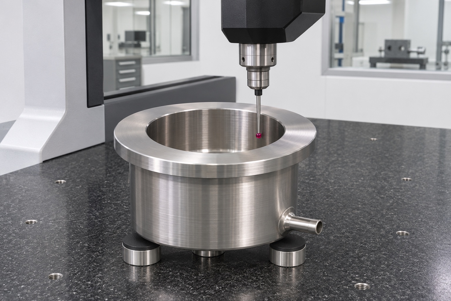
Bench checks and excluded conclusions
A dry check using an identified inert reference could reveal geometric interference at the cavity or mounting interface. A drain passage check could identify an obvious blockage. Neither would establish carryover performance, residue removal, reagent resistance or analyzer accuracy. The example deliberately separates these conclusions so a manufacturing record is not mistaken for system validation. If an engineering team needs a fluid trial, that trial requires its own safe fixture, procedure and acceptance criteria. It should not be improvised on an installed clinical analyzer, and a successful observation should not be generalized beyond the conditions under which it was made.
Handling an unexpected finding
Suppose the internal examination reveals a lip at the drain breakthrough. The response would be to identify the affected part, preserve its condition and review the permitted correction. After correction, the relevant hole, cavity and edge characteristics would be inspected again. If the geometry cannot be corrected within the drawing, seek a design disposition rather than quietly enlarging the outlet. This is a decision example, not a claim that a production defect occurred or was resolved. A good small-batch process makes such decisions traceable so corrected parts cannot be confused with parts accepted under the original inspection sequence.
Packaging and record separation
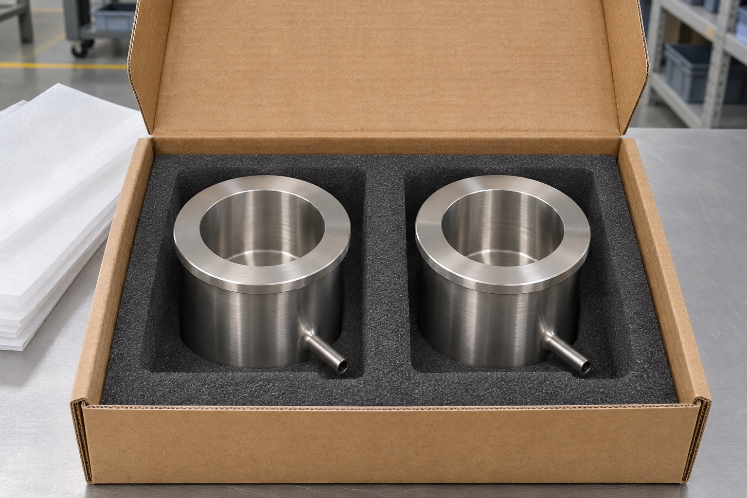
The packaging proposal places each cup in its own protective position, keeping the rim and drain clear of pressure from other parts. Any closures or wrapping materials should meet the agreed handling specification. The package can carry part identity and revision information while the inspection record remains associated with the same batch. Protective packaging is not presented as sterile packaging or evidence of analytical cleanliness. If cleanliness controls are required, they must be specified with appropriate acceptance evidence. Separating these requirements prevents an ordinary shipping solution from being described as a medical qualification that the example has not established.
Information needed to turn the example into an order
To develop this example into a real manufacturing request, provide the final drawing, stock requirement, quantity, treatment condition, inspection list and handling constraints. Identify the dimensions whose relationship to the mounting reference matters most. Resolve whether the drain is integral, threaded or connected by a separately specified fitting before quotation. Agree how first-article approval will be recorded and how later revisions affect the batch. The value of the example is a clear discussion of the proposed machining and evidence, not a promised result. Production acceptance would still depend on the approved specification and the actual records generated for the order.
FAQ
Is this a completed customer delivery?
No. It is a representative manufacturing example with a proposed process and inspection plan, not a verified delivery or performance report.
What would identify the stainless material?
The approved purchase specification and the required material documentation should identify 316L stock and connect it to the actual manufacturing batch.
Does this case specify a universal bore tolerance?
No. The application drawing must define the required size and geometric relationships. No unverified tolerance capability is claimed.
Why is the drain connection construction important?
An integral outlet, a simple radial opening and a separate fitting require different manufacturing and inspection details. The drawing must identify the intended construction.
What happens after internal deburring?
Reinspect affected geometry and edge condition using the approved method. Earlier measurements do not automatically remain valid after correction.
Can the part be installed based on this article?
No. Installation requires a released component specification and the device owner's applicable approval process. This example does not establish compatibility.

tanghangyun@oemach.com