
This right proximal phalanx is a long, lightweight robot-finger link. Precision joint features sit at both ends, while thin walls and pockets reduce mass through the center span.
The manufacturing priority was to preserve the spacing and axis relationship between the two joint ends after extensive lightweighting. OEMach established the functional holes and common datum first, then planned the cavities and outside profile around that relationship.
Project Snapshot
| Item | Project detail |
|---|---|
| Application | Right proximal phalanx link for a robot dexterous hand |
| Material and condition | 7075 aluminum, delivered in natural precision-machined condition |
| Key features | Long thin-wall span, lightweight pockets, two joint ends, small threads and transverse holes |
| Control focus | Drawing callouts including 5g6, 4H7 and 2JS7 features, 0.01 mm geometric relationships, bore spacing and free-state deformation |
Start With The Two Joint Ends
The joint features at both ends transfer motion and define the finger link. The thin center structure reduces inertia, but its geometry is secondary to the spacing and orientation of those functional ends.
OEMach identified the fit features, bore spacing and shared datum before programming the pockets. The specific 5g6, 4H7, 2JS7 and 0.01 mm callouts were controlled as released-drawing requirements for this part.
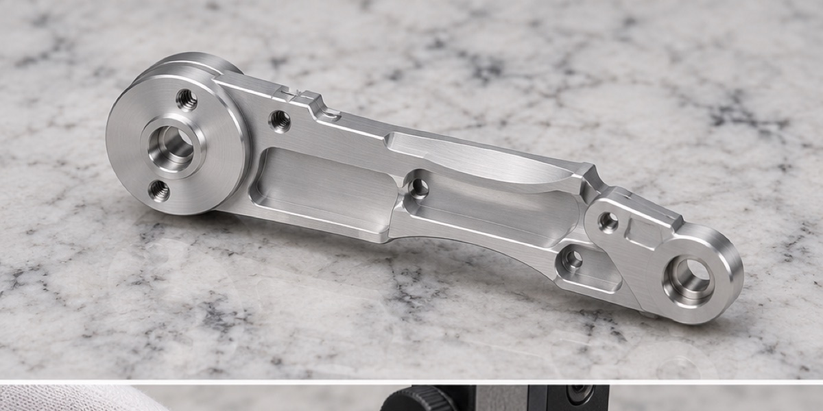
Two functional joint ends are connected by a long lightweight web, making bore spacing and axis relationships sensitive to asymmetric stock removal.
7075 Strength Does Not Eliminate Thin-Wall Movement
A long span can move as internal stress is released, even in high-strength 7075 aluminum. Unequal wall thickness and the heavier joint blocks amplify changes in bore spacing when one side is machined too aggressively.
Roughing alternated between sides in balanced layers. Finishing stock remained around the joint ends and center contour, and an unclamp-and-recheck point allowed the free-state shape to be observed before final features.
Finish The Fits After The Structure Stabilizes
The outside profile, cavities and datum faces moved through rough and semi-finish stages before the critical fit features were completed in a common location. This reduced the chance that later lightweighting would move a finished bore or shaft feature.
Guided tools were used for small threads and transverse holes. Entrance chamfers remained limited, and root clearances were deburred without creating sharp edges that could damage tendons or cable elements.
Inspect Both Ends Together
Small-size gauges or pins confirmed local bore and shaft fits. Bore spacing, axis parallelism and the drawing's geometric relationships were evaluated in one coordinate system rather than measuring each end independently.
The thin-wall contour was rechecked in the free state with low measuring force. Small holes, pocket roots and intersecting edges received magnified burr inspection.
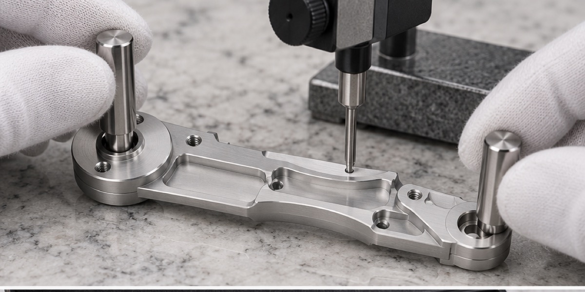
Small gauges verify local fits while low-force geometric inspection evaluates bore spacing, axis parallelism and the project-specific 0.01 mm relationships.
Deburring Must Protect Fits And Lightweight Edges
Joint entrances need a smooth assembly lead without reducing effective fit length. Pocket and rib edges must be safe for hand assembly and must not abrade moving tendon or cable paths.
The natural machined finish makes local scratches and impact marks visible. Final inspection followed cleaning, and abrasive paper was not used casually on functional bore edges.
Lead Time Includes Stress Release And Bore-Spacing Checks
The source project used 5 to 8 working days as a prototype planning range and 8 to 12 working days for small batches. Paired inspection, full dimensional reports or later surface treatment require separate confirmation.
The part was sealed in a clean bag and supported at both joint ends. The center span carried no bending load, and multiple parts were not stacked directly on one another.
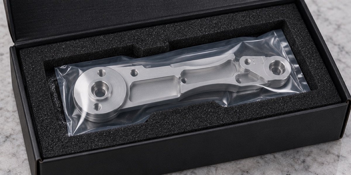
Foam carries both joint ends while the lightweight center span remains free from bending load and direct stacking.
Case Summary
Lightweighting and joint precision were managed as one problem. Balanced removal, intermediate release, delayed fit finishing, common-coordinate inspection and end-supported packaging preserved the function of the 7075 proximal phalanx.
FAQ
Why can a strong 7075 link still deform?
Strength does not remove residual stress or the flexibility created by long thin walls and large material removal.
Why are both joint ends inspected together?
The finger mechanism depends on their spacing and axis relationship, which cannot be proven by checking each local diameter alone.
Why are fit features finished late in the route?
Later pocketing and profile removal can release stress. Finishing after stabilization protects the final bore spacing and fit.
How is the thin center span protected in shipment?
Foam supports the two joint ends while the center span remains unloaded, and parts are not stacked directly.
Ready to get a quote for your CNC machined parts?
Submit your engineering drawings to qiancj@oemach.com. We support prototype sampling and small-batch production with strict tolerance control.