
This lead-screw bearing seat is smaller than many conventional fixtures, yet its bearing bore, mounting base and end hole carry a project-specific 0.01 mm relationship. The central challenge is holding and measuring the part without changing it.
OEMach treated the H7 bearing bore as the functional center and used the base and end feature as locating references. Part size did not reduce the need for datum planning, controlled clamping, dedicated gauging and burr inspection.
Project Snapshot
| Item | Project detail |
|---|---|
| Application | Lead-screw bearing support for a robot dexterous-hand mechanism |
| Material and condition | 6061-T6 aluminum, delivered in natural precision-machined condition |
| Key features | Stepped H7 bearing bore, slender base, small end hole, local steps and bore-entry chamfer |
| Control focus | Project-specified 0.01 mm parallel/perpendicular relationships, low clamp force, micro-burr removal and clean packaging |
A Small Part Still Needs A Full Datum Strategy
The stepped bearing ring locates the lead-screw bearing, while the base establishes height and orientation in the hand. The small end hole completes the mounting relationship. An acceptable bore diameter alone would not ensure the correct lead-screw attitude.
The process therefore referenced the bore axis to the base and kept the end feature in the same functional chain. The exact H7 and 0.01 mm requirements were treated as drawing-specific conditions, not general claims for every miniature part.
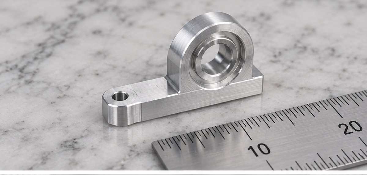
The compact part combines a stepped bearing ring, slender base and small mounting ear; the bore axis must remain related to the base datum.
The Fixture Is Larger But The Clamp Force Is Lower
The slender base and one-sided bearing ring can tilt or deflect under local pressure. Profiled soft jaws and small locating contacts supported the part while keeping clamp loads away from the weakest ring section.
After roughing, the part was released and relocated before the base and H7 bore were finished. This prevents a strong fixture from pressing the part into an apparently acceptable shape that disappears after release.
Establish The H7 Bore In Controlled Steps
The base and bearing-ring profile were stabilized first, then the H7 bore was finished from the base datum. Small holes and local steps followed so their chips and burrs did not contaminate the finished bearing seat.
The finishing tool was managed separately for bore size and wall condition. The entrance chamfer was limited to assembly guidance and deburring so the effective bearing-fit length remained intact.
Miniature Inspection Requires Low Measuring Force
Pin gauges or a dedicated small-bore gauge confirmed the H7 fit. Parallel and perpendicular relationships between the base and bore axis were checked with a low-force method and the part was not held by hand during geometric inspection.
The bore, end hole and step roots were examined under magnification. A micro-burr may not change the reported basic size, but it can damage a bearing, cable or tendon element during assembly.
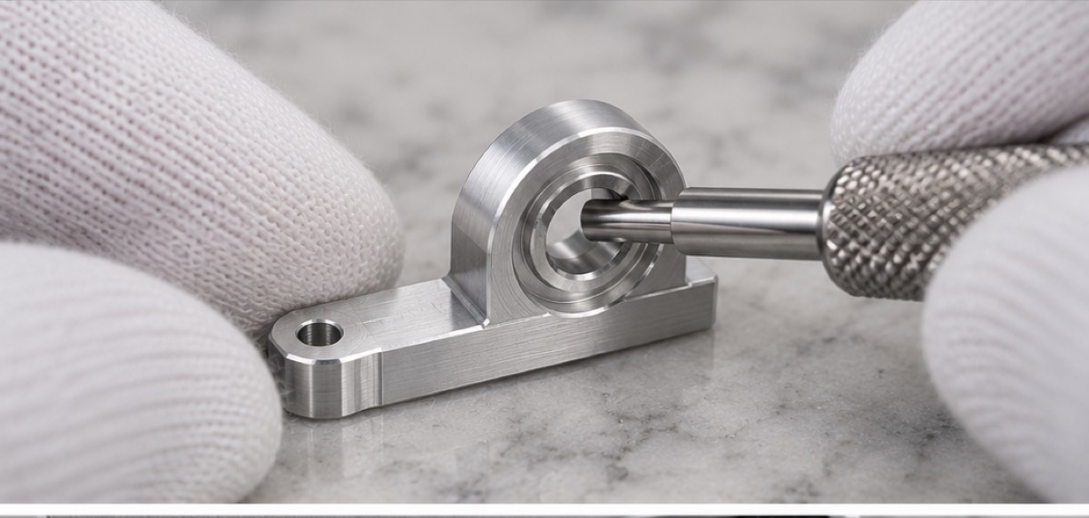
Dedicated small-bore gauges verify the fit without hand pressure or excessive measuring force distorting the miniature support.
Natural Finish Still Has Surface Requirements
The source case was delivered in the natural machined condition, with emphasis on no burrs, no scratches, a clean bore and consistent tool marks. If a future order requires anodizing, masking or post-coating bore allowance must be reviewed separately.
No color treatment does not mean the surface is uncontrolled. Raised impact marks and rolled bore edges become especially visible and functional at this scale.
Lead Time Includes Gauging And Micro-Deburring
The source project used 4 to 6 working days as a prototype planning range and 7 to 10 working days for small batches. Fixture preparation, gauge verification and magnified deburring consume real time even when machine cycle time is short.
Each cleaned part was sealed in a small bag and placed in an individual foam pocket. The bearing ring remained unloaded and the miniature part could not move or become lost inside the shipping box.
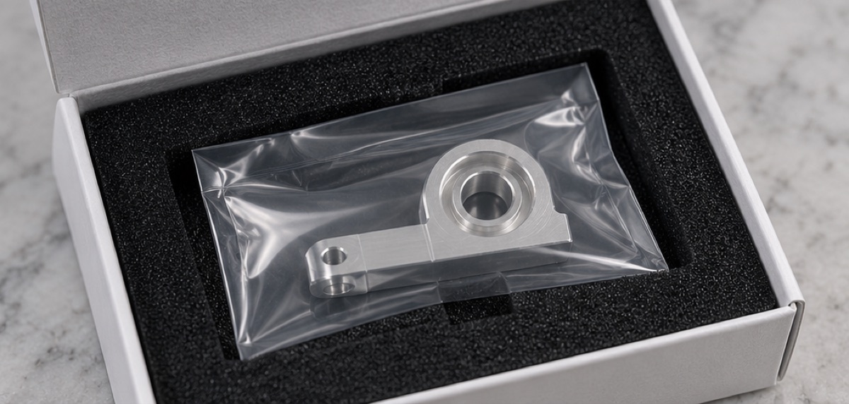
A sealed bag and dedicated foam pocket protect the bearing ring, bore edge and natural machined finish from pressure and loss.
Case Summary
The miniature bearing seat required more controlled handling, not less. Low-force fixturing, a staged H7 bore process, low-force inspection, magnified burr checks and individual packaging prepared the component for direct dexterous-hand assembly.
FAQ
Why can a miniature bearing seat be difficult to machine?
The part has little stiffness and little clamping area, while the bearing bore and base still require a precise functional relationship.
How is an H7 micro bore verified?
Use a calibrated pin or dedicated small-bore gauge for size and a separate datum-based method for the bore-axis relationship.
Why is low measuring force important?
Hand pressure or excessive probe force can move or tilt a small flexible part and create a false result.
Does natural finish require less final inspection?
No. Burrs, scratches, bore cleanliness and edge condition remain acceptance characteristics even without anodizing or plating.
Ready to get a quote for your CNC machined parts?
Submit your engineering drawings to qiancj@oemach.com. We support prototype sampling and small-batch production with strict tolerance control.