
Describe the sample and its limits
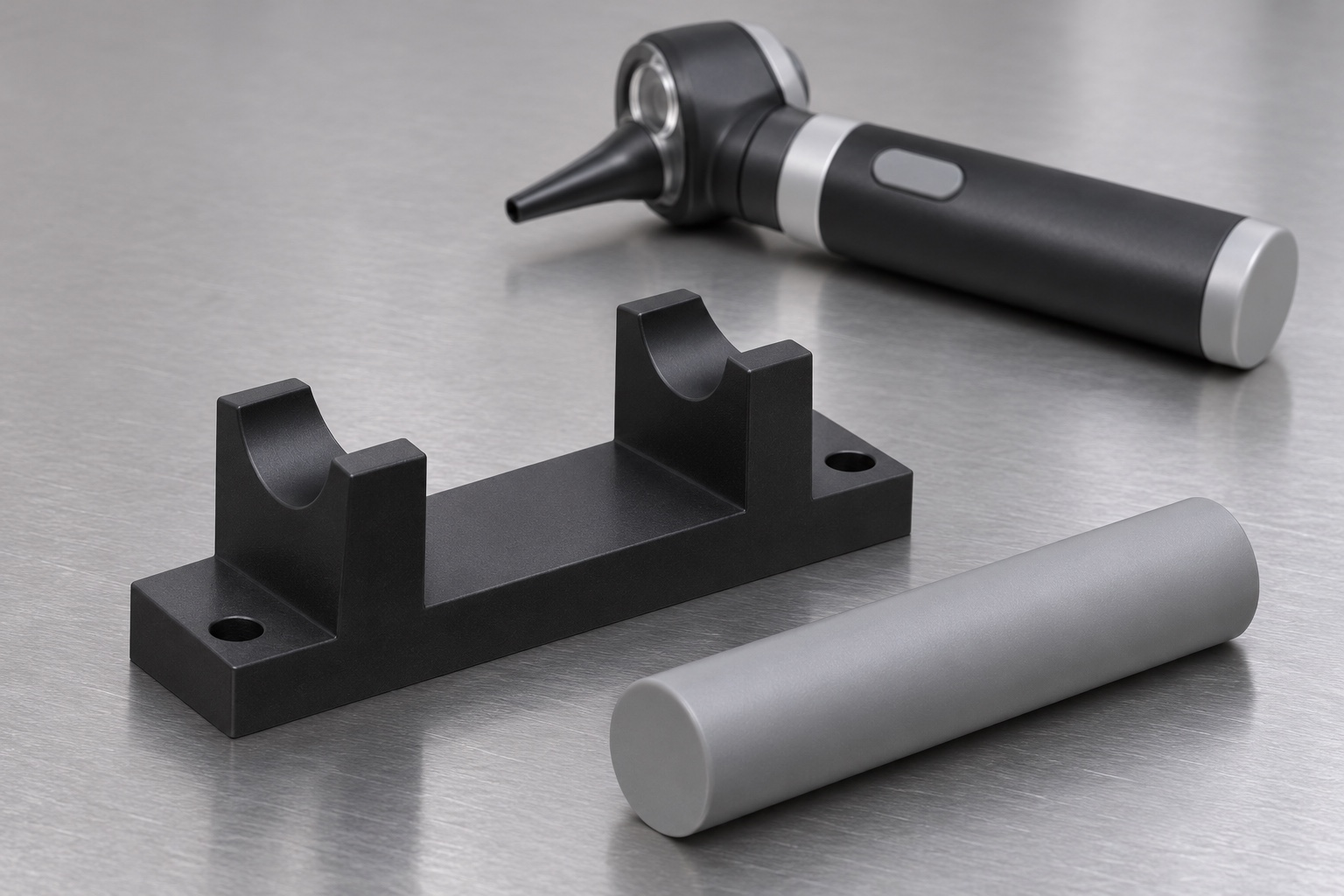
This representative CNC example considers a black POM-C block with two raised supports, a shallow groove on each support and two fixture mounting holes. The intended trial uses a rigid, unpowered cylindrical handle surrogate on a bench. It is not a charger, a real otoscope replacement part or a customer delivery. The illustrations show a possible shape and manufacturing approach, not an approved design or a measured result. Any fit claim would be limited to the stated bench references and would not establish compatibility with the instrument shown in the background.

Set two contact zones before detailing the grooves
The example uses two regions along the dummy cylinder so the unsupported middle can clear the block. A drawing would specify the length and location of each contact and how the dummy can be removed. Keep switches, seams and dummy connectors outside the usable support area. If one end of the dummy has a different diameter, state which groove it enters and how the setup is oriented. The initial order should identify which surfaces may carry the part and where there must be no contact, even at the limits of the approved envelope.
Identify the mounting state and origins
The block sits on its underside and two holes can retain it on an agreed trial plate. The concept does not use screw clearance to define exact side position. If the inspection depends on repeated location, a separate reference should be identified on the drawing. Record whether the cradle is measured free or mounted. A burr under the base or an uneven test plate could tilt both saddles. Measure each support relative to a common reference so the two values can be compared, not relative to unrelated fixture surfaces.
Record the polymer grade and lot
The candidate material is POM-C, and a real order would state grade, stock form and material documentation. Black color is not proof of any of those properties. Preserve the stock lot through machining and identify any insert or surface treatment in the final condition. A separate liner could change the height and must be included in a mounted check if the approved design calls for it. This example supplies no electrical insulation, chemical compatibility, charging safety or clinical suitability evidence. It addresses only a machined support for a nonfunctional surrogate.
Establish stable support during roughing
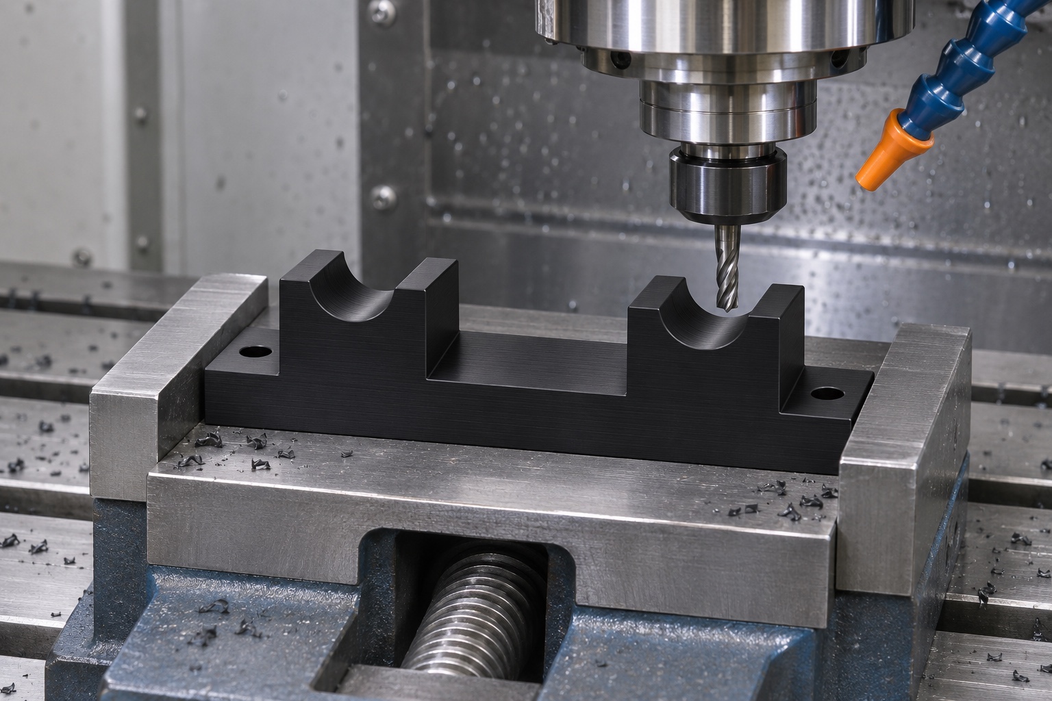
A candidate process faces the base, establishes lateral references and roughs around the two raised saddles while leaving allowance at the grooves. Support the stock near the cutting loads without pinching the narrow walls. Release and check the blank before deciding how to finish. If the base changes shape, inspect it again rather than flattening it in the fixture by force. The machining photo is explanatory only; it does not specify tool diameter, cutting speed or production workholding. Those choices depend on the actual drawing, grade and equipment.
Finish the two profiles and mounting holes
Finish the groove profiles using a common origin where practical. Locate the holes separately from the contour, and verify the intended reference if a setup is transferred. Keep the ends of the grooves clear of a dummy shoulder and avoid tool marks raised into the contact. A permitted edge break should not change usable support length or depth. Verify the base and hole exits after deburring. If the approved drawing calls for an axial stop, check its relation to the same reference instead of placing it by visual alignment with the grooves.
Use named inspection stations
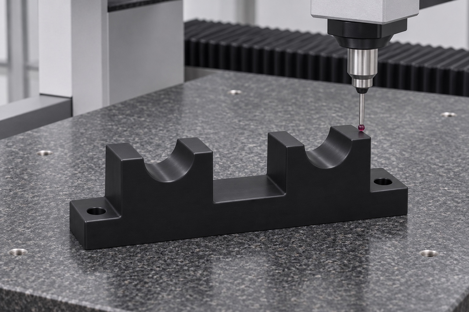
An example geometry report would list the underside condition, each groove profile and the relation between the groove centers. Identify the measured sections so a probe does not contact an edge break or radius transition. A cylindrical master across both supports may help compare seating, but it must be identified and does not replace required contour measurements. Keep dimensions under fastening distinct from free-state measurements. The inspection image contains no values or evidence of conformity. It shows a possible way to approach a relevant surface on a bench.
Place a rigid dummy on an unpowered bench
An initial trial would place the identified surrogate onto both supports without touching a switch, connector or other excluded area. Record insertion and removal observations and whether the body settles without force. Repeat after fully lifting it off and use the same support conditions. If the dummy rocks, examine its diameter and the two contact zones before changing the groove. This observation can reveal a mechanical mismatch in that setup. It does not establish retention under operating loads, electrical performance or whether a named otoscope model can be used with the cradle.
Diagnose a rocking or tilted condition
Check for debris under the block, raised marks in the saddle, unsupported base regions and mismatch in the dummy revision. Compare a reading near each support from the same origin. An apparent tilt that changes when the dummy is reversed may require reviewing the reference rather than the fixture. If an approved correction is made, repeat measurements and placement under the original documented conditions. Do not change the design to suit one convenient sample without the owner's approval. A successful second fit is meaningful only if the cause and change are recorded.
Clean and mark outside functional areas
Remove loose chips under the agreed receiving process and inspect the saddle entrances, base and mounting holes. Keep labels and adhesive off the support zones and verify any permitted marking after handling. Note lot, revision and final state in the report. A visual check can identify debris or damage but does not establish clinical reprocessing or a controlled cleanliness class. Any use near a working instrument and any cleaning requirements for that instrument stay under the equipment owner's control, not the supplier's bench-fixture handling instructions.
Pack the block and reference separately
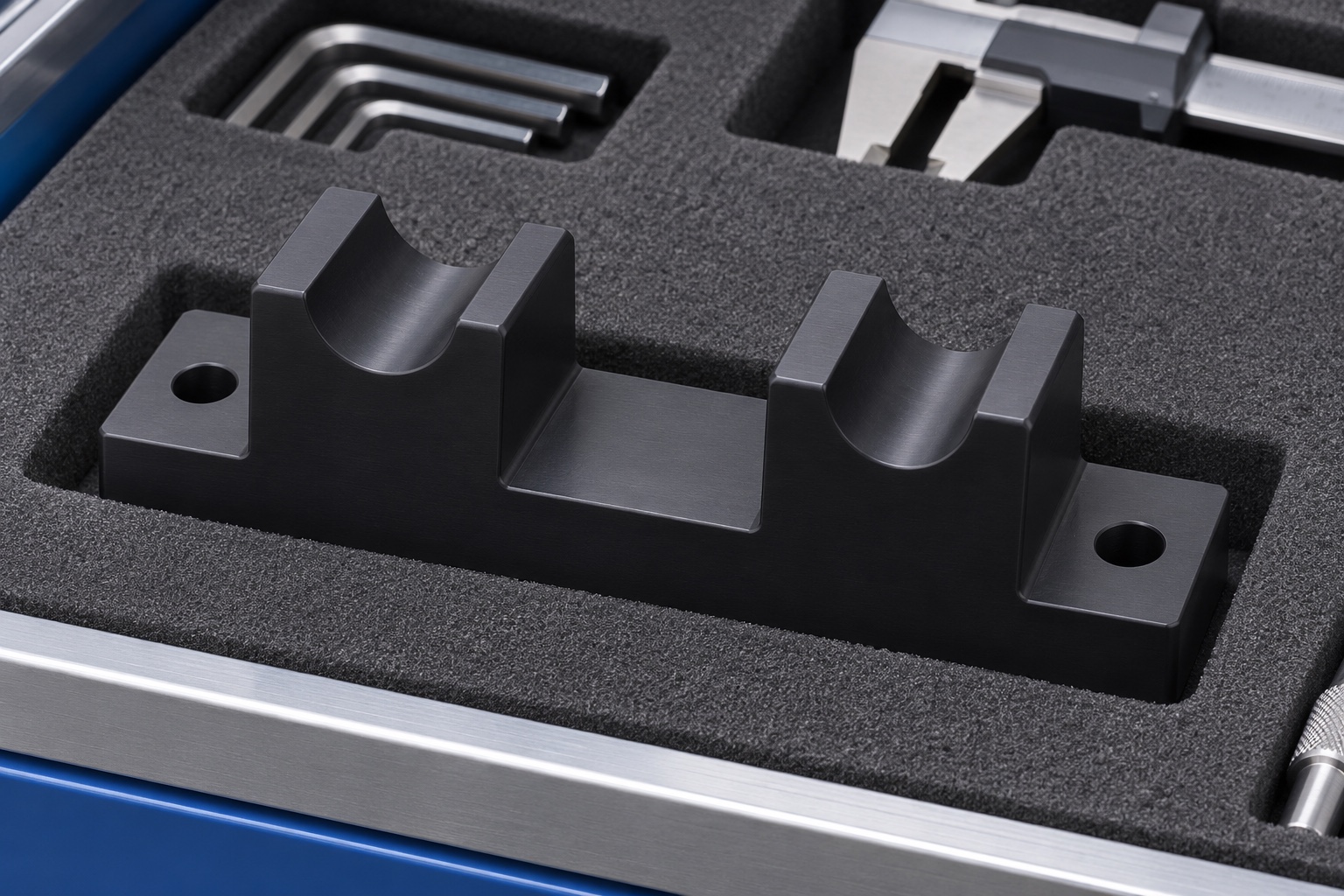
Support the cradle at exterior surfaces that can bear the shipping load without pressing on the grooves. Keep hardware and dummy parts in separate pockets. Tie the package to the drawing revision and inspection record. At receipt, check for visible damage, shifted packing or debris before relying on the previous results. If a reference arrived with the fixture, confirm its identifier and condition separately. The shown protection concept is ordinary packaging, not proof of sterile delivery, a controlled environment or a validated storage duration.
Define what a real manufacturing order would release
The actual order would require the cradle and surrogate drawings, material grade, intended contact zones, support conditions and inspection instructions. The supplier can document geometry and a separate unpowered fit observation. Any device-specific compatibility, electrical function or clinical use requires separate verification by the equipment owner. No customer identity, shipment, certification or measured result is claimed here. The example demonstrates a repeatable way to identify, make and check a two-saddle support while keeping its evidence within the stated mechanical scope.
Manufacturer background reference: www.hillrom.com.
FAQ
Was this fixture delivered to a customer?
No. It is a representative CNC example with illustrative pictures, not a customer shipment or evidence of an approved accessory.
What do the two saddles support?
They support defined exterior regions of an inert cylinder. The actual contact lengths and clearances would be stated on a controlled drawing.
Do the holes position the fixture precisely?
Not by default. They retain the block; a precise and repeatable location requires a separate specified datum or locating feature.
Can a fit check establish charging compatibility?
No. The trial is unpowered and checks mechanical seating only. It does not test a charger, battery or operating device.
What if the dummy rocks?
Check both support zones, the base, debris and dummy dimensions before changing the contour. Record any correction and repeat the affected checks.
Is the cradle sterile or cleanroom packaged?
No such claim is made. The illustrated insert only protects functional surfaces from ordinary handling damage.

tanghangyun@oemach.com