
The right-rear steering motor drive-end seat is geometrically mirrored from the left-hand component, but it cannot be treated as an automatically verified copy. Tool approach, fixture support and directional features all change with orientation.
OEMach created a separate program revision, zero-point instruction and first-article report for the right-hand 45 steel seat. The process addressed both mirror-direction errors and reversed cutting loads before paired delivery.
Project Snapshot
| Item | Project detail |
|---|---|
| Application | Right-rear drive-end seat for a robot steering motor module |
| Material and finish | 45 steel with black zinc plating; corrosion requirement recorded as 72 hours without red rust |
| Key features | Tall upright, stepped large bore, base hole group, side threads, dowel holes and directional steps |
| Control focus | Mirror orientation, bore axis to base, fixture loading, independent first article and paired identification |
Mirror Geometry Does Not Define The Manufacturing Process
A mirrored CAD model reverses shape, but it does not automatically establish safe tool approach, clamping force or inspection alignment. The right-hand part has different access around the high wall and side features.
OEMach assigned the right-rear seat its own controlled program and setup sheet. The left-hand approval was not used as a substitute for a right-hand first article.
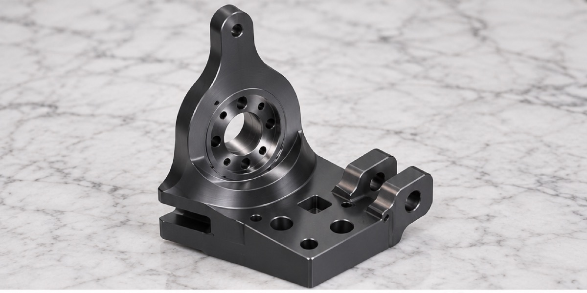
The mirrored steel seat has its own tool access, support direction and orientation-sensitive hole pattern even when nominal geometry matches the left-hand component.
The Fixture Prevents Wrong Orientation And Wrong Loading
Asymmetric locating blocks allow the component to enter the fixture only in the intended direction. Support is placed close to the large-bore cutting zone to reduce vibration and wall deflection.
Distributed clamping across the base avoids overloading one side. After roughing, the part is released and rechecked so the base and bore retain enough finishing allowance in a free condition.
The Bore Axis And Base Remain The Main Datum Chain
The base and primary locating holes are established before the large bore and annular face are finished. Small holes, side threads and slots follow after the main axis is defined.
This sequence allows the bore axis to be measured from the actual base coordinate system and lets left- and right-hand results be compared by function without forcing the two parts to share compensation values.
The Right-Hand First Article Checks Directional Features
In addition to the bore, base and hole group, the right-hand first article verifies side-hole direction, dowel position, local steps and the traceability area. These are frequent failure points when mirror logic is applied incorrectly.
The inspection report uses the right-hand assembly coordinates. Data is not flipped into a left-hand template, which reduces the risk that reversed features reach the customer's assembly line.
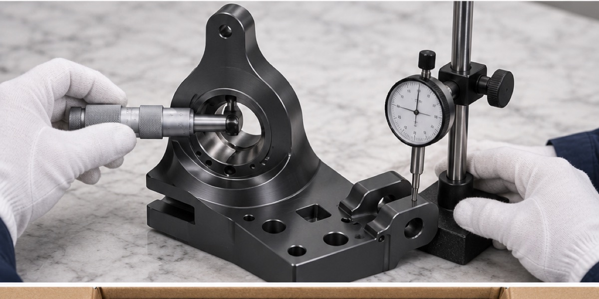
The right-hand assembly coordinate system is used to verify bore axis, base, side holes, dowel locations and directional features.
Post-Plating Checks And Pair Control Close The Loop
After black zinc, the bore, dowel holes and threads are rechecked along with coating uniformity and the project record for 72 hours without red rust. Protected fits and mating surfaces must remain clean.
For paired orders, quantity, hand identification and order grouping are checked together. A final anti-mix review is completed before the parts enter separate foam positions.
Lead Time And Delivery Depend On Both Hands Passing
The source project used 7 to 10 working days for prototype planning and 10 to 15 working days for small batches. When both hands are produced together, shipment is scheduled only after both groups complete inspection and plating review.
The right-rear part receives a dedicated, clearly oriented foam cavity. The box label and internal packing list preserve the same hand and order identification.
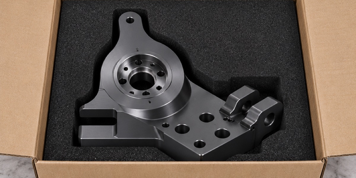
A clearly oriented foam pocket protects the black-zinc finish and prevents right- and left-hand components from being mixed during delivery.
Case Summary
Reliability in a mirrored steering end seat comes from independent verification, not from copying a program. Separate revision control, physical fixture error prevention, right-hand first-article inspection and paired delivery checks made the right-rear component traceable through assembly.
FAQ
Why does a mirrored part need a separate first article?
Mirroring reverses coordinate signs, tool access and fixture loading. A separate first article verifies the actual right-hand process and directional features.
How does the fixture prevent a left-right loading error?
Asymmetric locating blocks and physical keys allow only the correct orientation, while part identification provides a second control.
Can inspection data simply be mirrored from the left-hand report?
No. The right-hand part should be measured in its own assembly coordinate system so directional errors remain visible.
How are paired components protected from mixing?
Hand identification is checked against the order and packing list, then each version is placed in a dedicated oriented foam position.
Ready to get a quote for your CNC machined parts?
Submit your engineering drawings to qiancj@oemach.com. We support prototype sampling and small-batch production with strict tolerance control.