
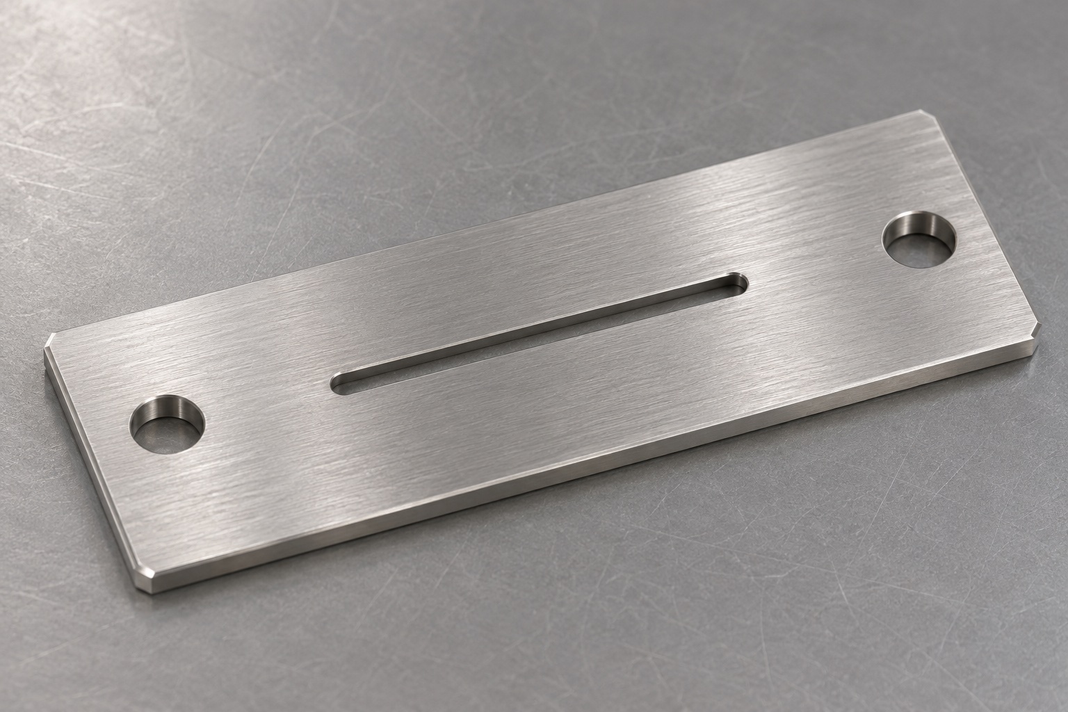
A representative manufacturing example
This example describes a proposed 316L slit plate for the dry optical compartment of a diagnostic photometer. It is not a customer delivery, a tested optical design or a medical certification. The illustrative plate is rectangular with a narrow central through opening, rounded slit ends and two plain mounting holes on the long centerline. Its exterior corners are lightly relieved. The geometry makes it possible to discuss aperture production and inspection separately from any performance claims for the instrument in which such a plate might be used.

Resolve the mounting scheme
In the scenario, a defined broad face seats against the holder, while a long side and an end establish the chosen inspection orientation. The two holes provide fastener clearance. If the real holder instead used pins to locate the plate, the datum assignment would have to change to reflect that installation. The example assumes no locational function for the plain holes. Review the assembled orientation early: if the same two holes allow the plate to be flipped, the design must decide whether the two faces are functionally interchangeable or require a mistake-proofing feature.
Write down the useful aperture
The aperture would be specified by width over a named straight portion, defined end transitions and a positional relationship to the installed references. The drawing should distinguish the acceptable internal edge from any break permitted on the exterior perimeter. The center-to-center spacing of the two mounting holes does not prove that the opening is centered. Use identified stations along the opening and state whether a face boundary or the through silhouette is being accepted. The concept illustrations intentionally omit measurements; no proposed nominal or limit should be extracted from image proportions.
Prepare the blank and support it
The stock would be identified as the specified stainless grade and form using material documentation, not its brushed appearance. A planning step would confirm that the blank can support the desired plate thickness and reference face after preparation. Establish outside references and mounting holes with support that avoids bending the thin material or producing an uncontrolled exit burr. Depending on the approved route, the part can remain attached to a larger carrier until the aperture is made. Support and access should be reviewed together so the cutting path remains clear.
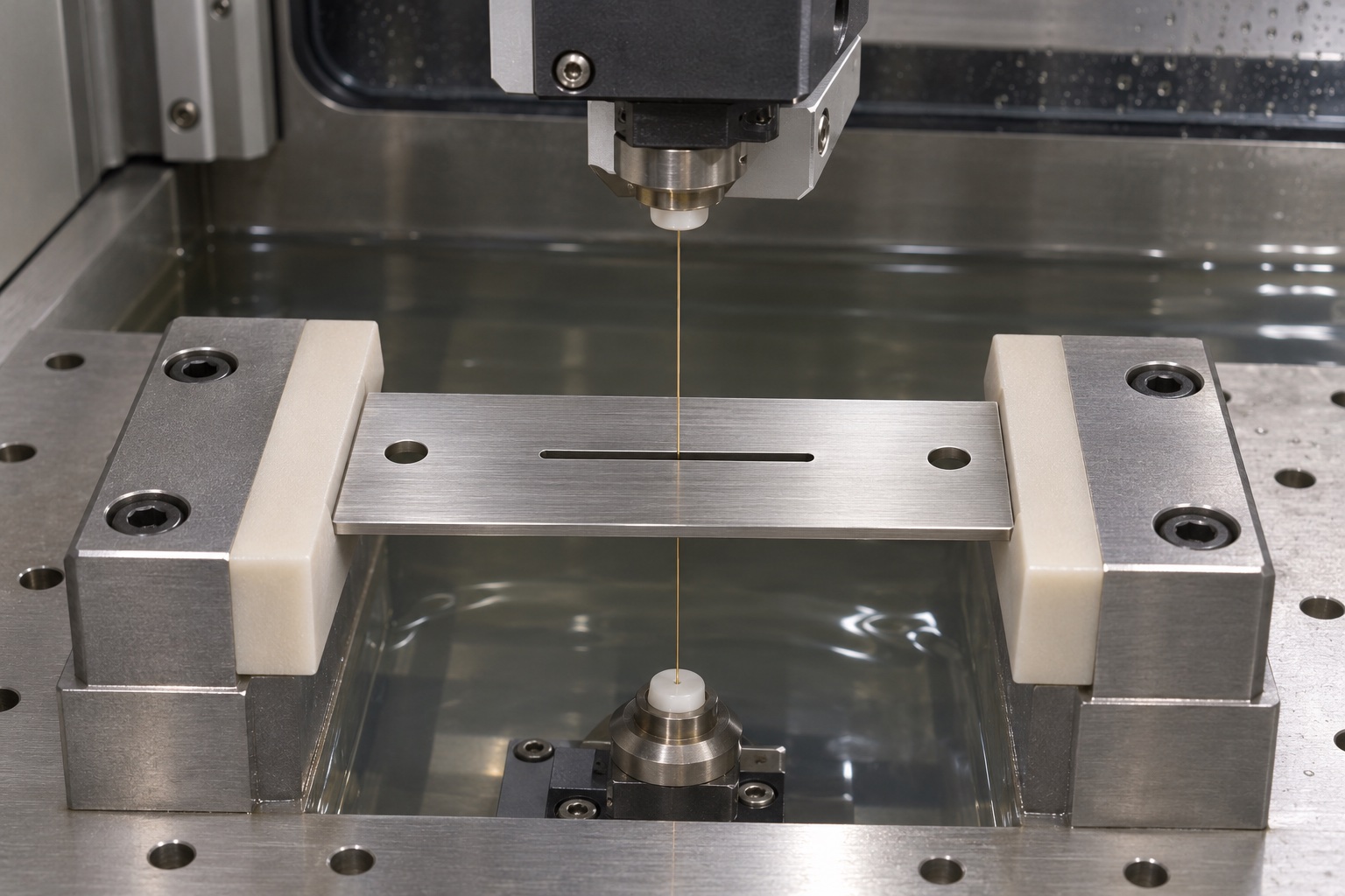
Plan a closed wire EDM contour
A candidate route places the wire start inside the material that will become the opening. The shop would check whether the start feature and wire threading method can fit within that region. The plan must also manage the cutout so it cannot move into the finished edge during separation. Whether a rough and finish sequence or a different cut strategy is suitable depends on the actual machine and requirements. The illustration shows the process concept, not the fixture, electrical setup or an instruction for operating a wire EDM machine.
Inspect after release from the fixture
The plate would be allowed to reach its agreed inspection state after being removed from the machining supports. Inspect seating face condition and form on supports that do not force it flat. If the released shape does not meet the drawing, record the discrepancy before attempting an adjustment. A local scratch on the aperture edge can matter even when the whole plate is nominally flat. Separate the flatness or seating checks from the opening measurements so that a good result in one category cannot conceal a defect in the other.
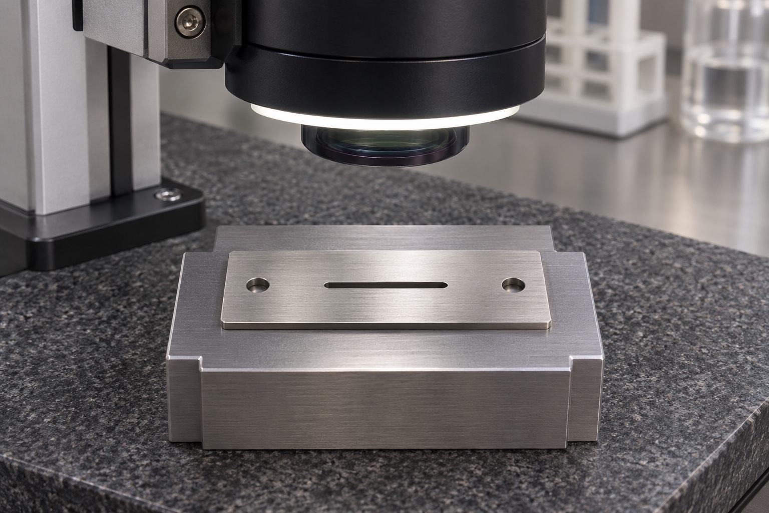
Use a calibrated vision recipe
The proposed dimensional method would use a calibrated vision system with the plate oriented to a defined face and the specified support condition. Transmitted illumination can establish a through silhouette; reflected illumination may be used separately for face-edge review. The recipe would store magnification, focus and edge thresholds along with station definitions. Compare repeated measurements or use an appropriate reference artifact to assess measurement agreement. The generated inspection image is not a dimensional report; it provides no readings, acceptance result, instrument accreditation or measured uncertainty for this proposed part.
Treat taper and edge shape explicitly
If both faces are critical, the inspection plan would compare them with orientation and viewing side recorded. A difference between apparent widths is a reason to examine the measurement setup as well as the cut. Light and focus changes can move the selected boundary in an image. If the drawing prohibits a raised lip or defines an edge condition, inspect it using a suitable method in addition to the width measurement. A failed edge is not repaired by unauthorized hand polishing, which could widen one section and undermine the accepted profile.
Keep finish and optical testing separate
The example depicts a bare metal finish only. A real project might require a different surface treatment to satisfy its optical and environmental requirements. Any treatment that contacts the aperture should be reviewed for its effect on the final geometry and measurable edge. Validate reflectance and instrument behavior by an agreed optical test on the proper assembly, not by comparing the plate's color to a render. A supplier can provide the specified material, geometry and process records without claiming that those records establish diagnostic accuracy or complete system compliance.
Perform a documented mechanical check
The proposed first build would mount the plate in a dummy holder that reflects the released references. Check that it seats without rocking and that the aperture stays in the intended orientation during assembly. If the hole pattern permits unintended rotation, report it to the design owner and resolve the drawing before proceeding. Do not use a tighter screw to flatten a nonconforming plate unless the approved assembly condition explicitly calls for restraint. The dummy setup addresses handling and fit only; it does not simulate an optical or clinical validation.
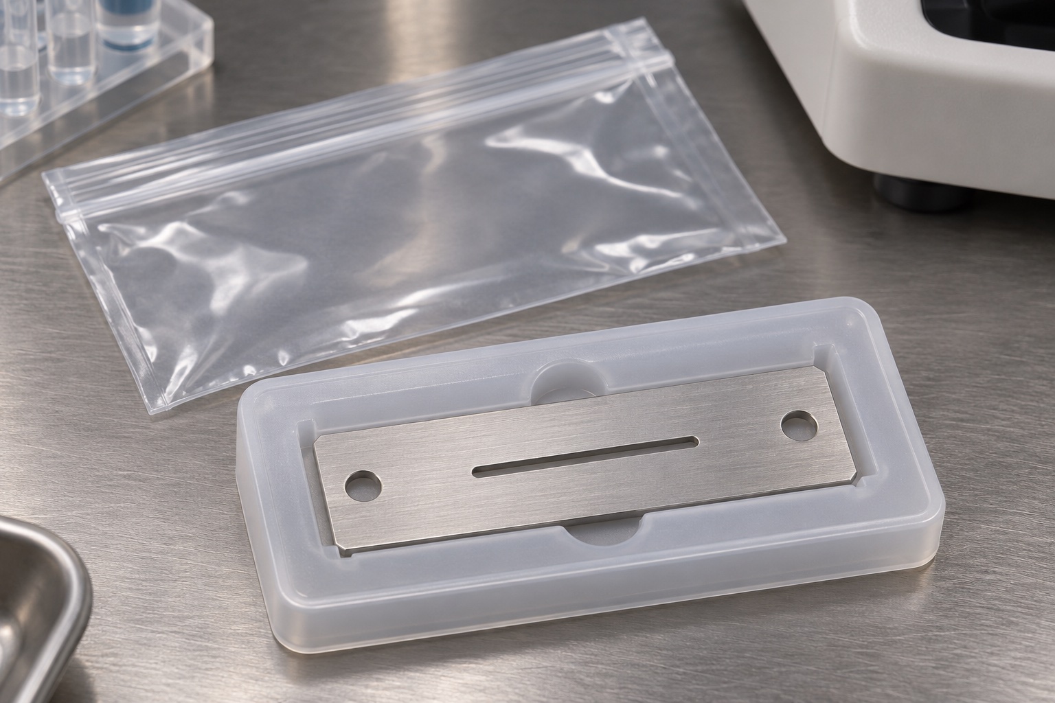
Preserve the part for receiving inspection
Package the plate in an individual protective pocket with support away from the slit. The receiving technician should be able to lift it by noncritical edges without sliding it against a hard separator. Keep adhesive, loose fibers and protective film residue away from the aperture unless an approved removal method is supplied. Mark the batch and drawing revision on the outer packaging. The example shows nonsterile protection. If the instrument has a controlled cleanliness requirement, put the relevant sampling and acceptance details in the order rather than relying on the pictured tray.
Collect the evidence before release
For a real order, the package would include the approved drawing revision, material traceability, process and finish requirements, an inspection report with each aperture station and the packaging specification. Any observations from the holder check should be attributed to the exact fixture and condition. Engineering must close deviations rather than accepting a part based on the resemblance of a rendered opening. This example demonstrates a way to organize the evidence: dimensional acceptance of the plate first, separately planned optical validation for the intended instrument, and controlled protection between the two stages.
Manufacturer background reference: www.makino.com.
FAQ
Is this an actual shipped photometer component?
No. This is a representative machining example with illustrative images. It does not report an order, measured results, an approved customer design or performance of a delivered medical device.
What geometry does the example include?
A flat rectangular 316L plate with one central narrow through slit, rounded slit ends and two plain mounting holes. It is an engineering concept; use a controlled drawing for dimensions, location, thickness and the approved edge specification.
Why keep the wire start inside the opening?
A start within the region removed by the contour can avoid adding a separate feature to the retained plate. The actual start location and threading method must fit the drawing, machine and available access. The picture does not define that setup.
Does a vision image prove the slit is in tolerance?
No. A calibrated system, documented view and approved edge convention are needed. Measure the stations specified on the drawing and record the method and side viewed. The image here illustrates inspection without presenting measurements.
Is a bare 316L plate suitable for every optical path?
No such claim is made. An instrument may require a specific finish, coating or absorption behavior. Specify it with the design owner and check the finished aperture separately from optical performance of the assembled photometer.
What should receiving inspection prioritize?
Verify the part and revision, then examine the aperture and seating face for transit damage without inserting material into the slit. Compare the dimensional report and package condition with the agreed order. Escalate a damaged edge rather than reworking it informally.

tanghangyun@oemach.com