
The challenge in this cross-roller bearing mount is not one difficult hole. It is the number and density of holes that must remain related to the same bearing axis and annular mounting face.
OEMach treated the 45 steel ring as a precision bearing locator rather than a perforated disc. The bearing seat and main face defined the process, while hole-pattern machining, deburring, black zinc plating and inspection followed that common datum.
Project Snapshot
| Item | Project detail |
|---|---|
| Application | Cross-roller bearing fixing mount for a robot steering joint |
| Material and finish | 45 steel with black zinc plating |
| Key features | Precision bearing seat, annular faces, 16-hole pattern, M4 threads, counterbores and local steps |
| Control focus | Bearing-axis datum, free-state face geometry, hole-pattern position, thread quality, burr control and post-plating fit |
Treat The Ring As A Bearing Locator
The central bore and shoulder locate the cross-roller bearing, while the annular face establishes axial seating. The surrounding holes apply clamping load and connect the mount to the joint structure.
OEMach defines the bearing seat and primary face first, then relates hole-circle diameter, angular spacing, hole depth and local steps to that functional system.
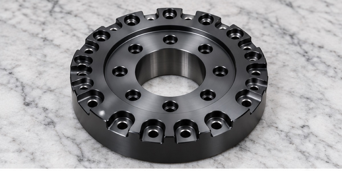
The central bearing seat, annular face, 16-hole pattern, M4 threads and local steps must all remain referenced to one rotational datum.
A Dense Hole Pattern Changes Ring Stiffness
Drilling, counterboring and tapping near the outer edge progressively remove material and alter local stiffness. If the ring is clamped at a few hard points, the annular face can move slightly after release.
Distributed face support, controlled clamp force and balanced hole sequencing reduce this risk. Cutting direction and tool entry are also planned around the close geometric relationship at the bearing seat.
Finish The Center And Faces Before The Hole Pattern
Both main faces and the central locating features are established first, with allowance retained for final bearing-seat finishing. Once the ring is stable, the 16-hole pattern, M4 threads, counterbores and local steps are completed in one referenced coordinate system.
Deburring is performed after each hole family rather than postponed until the end. This prevents chips from being trapped against a finished face during the next setup and protects counterbore edges.
Use One Center For First-Article Inspection
The CMM alignment uses the bearing seat and primary annular face, then evaluates the hole pattern, angular relationship, threads and steps from that common center. Local best-fit centers for each hole group would hide the actual assembly relationship.
The annular face is checked for flatness and runout in the free state. The bearing seat is checked for size, roundness and specified surface finish, and every small thread is verified with GO and NO-GO gauges.
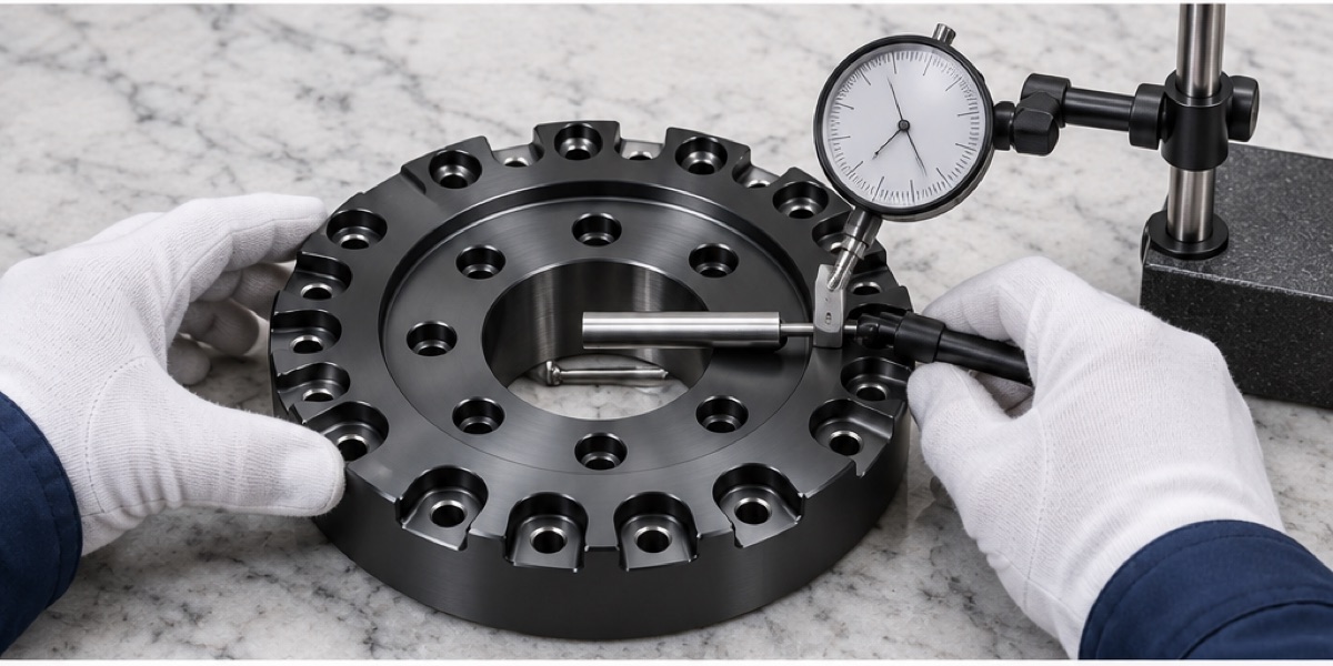
Bore geometry, face runout and the dense hole pattern are evaluated from the bearing axis and primary mounting face.
Black Zinc Needs Different Before-And-After Checks
Before plating, the bore, faces, threads and full-circumference burr condition are inspected and critical fits are protected. After plating, OEMach checks coating uniformity, bore residue, thread passage and any change at the functional seat.
When the order specifies 72 hours without red rust, the test method, rating and plating batch traceability are agreed before production. Excess deposit cannot be used to trade fit for corrosion resistance.
Inspection Time And Packaging Are Part Of Delivery
A practical reference is 6 to 9 working days for prototypes and 9 to 14 working days for small batches. A complete report for every hole requires dedicated CMM time and should be included in the confirmed schedule.
A profiled foam nest supports the ring without hard contact on the faces or counterbore edges. Multiple parts are individually separated to prevent finished hole edges from striking each other.
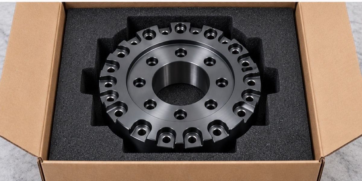
Profiled foam separates the precision faces and counterbore edges from hard contact during transport.
Case Summary
A cross-roller bearing mount is a precision locator organized around the bearing axis and annular face. Common datums, balanced material removal, staged deburring, one-center inspection and post-plating verification keep a dense hole pattern compatible with reliable assembly.
FAQ
Why must the 16-hole pattern be measured from the bearing seat?
The holes clamp and locate the mount around the bearing axis. Measuring them from an unrelated local center can hide position or angular error that appears during assembly.
Why is the annular face checked in the free state?
Concentrated clamping can temporarily flatten the ring. Free-state inspection reveals the geometry that will be delivered and helps distinguish fixture deformation.
What is checked after black zinc plating?
Bearing-seat condition, bore cleanliness, thread passage, coating uniformity, face particles and protected functional areas are checked again.
Does a full hole report affect lead time?
Yes. A dense hole pattern requires additional probing, feature evaluation and report review, so the inspection scope should be agreed during quotation.
Ready to get a quote for your CNC machined parts?
Submit your engineering drawings to qiancj@oemach.com. We support prototype sampling and small-batch production with strict tolerance control.