
This left-rear steering motor drive-end support connects a motor, bearing and lower mounting structure. Its critical requirement is not the outside profile, but the spatial relationship between the large bore axis, base plane and locating holes.
OEMach planned the 45 steel part around one three-dimensional datum chain. Roughing support, large-bore finishing, mirrored-part error prevention, black zinc protection and final inspection were included in the same delivery plan.
Project Snapshot
| Item | Project detail |
|---|---|
| Application | Left-rear drive-end support for a robot steering motor module |
| Material and finish | 45 steel with black zinc plating |
| Key features | Tall upright, large stepped bore, base hole group, dowel holes, side threads and local slots |
| Control focus | Large-bore axis to base datum, wall rigidity, mirrored orientation, post-plating fit and paired identification |
Start With The Base And Locating Datums
The base plane and locating holes establish the support on the steering module. The large bore then positions the motor or bearing axis above that base, while the side holes and steps complete the surrounding interfaces.
OEMach defines these functional references before programming so the bore, end face, dowel locations and base hole group can be inspected in one coordinate system.
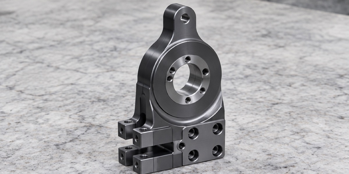
The tall wall carries a large stepped bore above a base with locating and threaded holes, so the bore axis must remain related to the mounting datum.
The Tall Wall Turns Bore Accuracy Into A Rigidity Problem
The large bore sits in a high wall above slots and separated mounting feet. Uneven stock removal can move the wall, while excessive clamp force can create a false-flat base and shift the bore axis after release.
Roughing, base finishing and bore finishing therefore use different support strategies. Support is placed near the actual load path, and the wall is backed during bore machining without forcing it into an artificial position.
Machine The Stable Datums Before Weakening The Part
The process first establishes the base and primary locating holes. A dedicated support then carries the upright while the large bore and its stepped face are finished. Local slots and side holes follow after the main datum chain is stable.
The bore-to-base relationship is checked immediately after bore finishing. Early data helps separate fixture error, tool wear and part relaxation instead of waiting until all small holes are complete.
Left And Right Parts Need Separate Error Prevention
Mirrored supports may share dimensions but not every setup direction, tool approach or coordinate sign. Program revisions and first-article records are therefore controlled separately for the left-rear and matching right-hand part.
Dowel location, hole-group direction and side features are common mirror-error risks. Physical fixture keys and clear part identification provide more reliable prevention than operator memory.
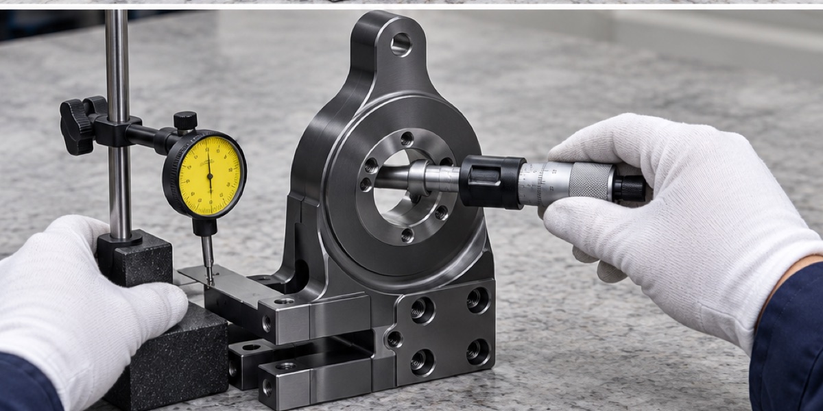
Bore size, axis relationship and base condition are checked from functional references instead of treating the upright and base as separate features.
Black Zinc Changes The Final Acceptance
Before plating, OEMach checks the large bore, dowel holes, base, threads and complete deburring, and protects functional fits as specified. After black zinc, bore residue, thread passage, coating uniformity, particles and runs on the base are rechecked.
If the order requires 72 hours without red rust, the test method, acceptance criterion and plating batch record are agreed in advance. Corrosion performance cannot replace verification that the bore and base still assemble correctly.
Lead Time And Paired Packaging
A practical reference is 7 to 10 working days for prototypes and 10 to 15 working days for small batches. Paired left/right delivery requires additional identification and matching time.
Profiled foam prevents direct pressure on the bore, base and dowel holes and keeps the upright from rolling. Left and right parts are placed in separate positions so receiving can route them directly to the correct assembly station.
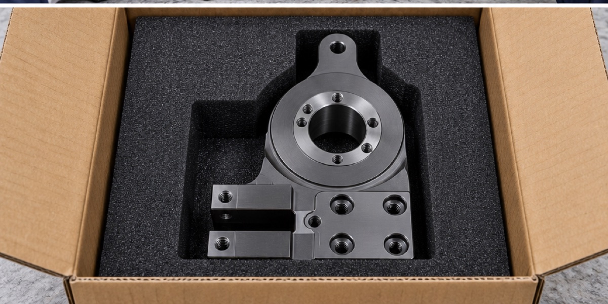
The foam prevents load on the bore, base and locating holes and keeps left- and right-hand parts separated for assembly routing.
Case Summary
The quality of this drive-end support depends on one stable datum chain from the base and locating holes to the large-bore axis. Controlled support, early in-process verification, mirrored-part error prevention and post-plating checks make the steel bracket ready for steering-module assembly.
FAQ
Why is the large bore not inspected by diameter alone?
Its axis must also be correctly positioned and oriented to the base and locating holes. A correct diameter with a shifted axis can still prevent assembly or create bearing misalignment.
Why are left- and right-hand first articles controlled separately?
Mirrored geometry changes coordinate signs, approach directions and fixture loading. Separate programs and records reduce the risk of reversed hole groups or side features.
What is checked after black zinc plating?
Functional bores, dowel holes, threads, base cleanliness, coating uniformity and any protected fit are checked again in the delivered condition.
How are the tall supports protected in shipment?
Profiled foam prevents rolling and point load, protects the bore and base, and keeps left and right components clearly separated.
Ready to get a quote for your CNC machined parts?
Submit your engineering drawings to qiancj@oemach.com. We support prototype sampling and small-batch production with strict tolerance control.