
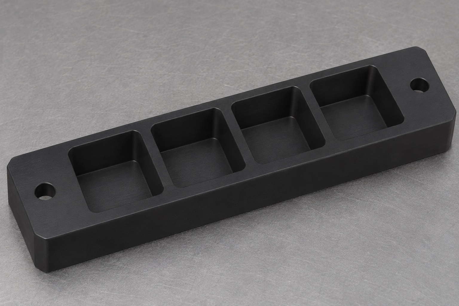
Scope of the representative component
This representative example proposes a black POM-C carrier for external support of identified closed cuvettes or similar approved containers inside medical laboratory equipment. The concept is a rectangular bar with four square blind pockets in one row and two plain mounting holes outside that row. It is not a documented customer delivery or a report of measured production results. The proposed scope includes mechanical manufacturing and inspection planning only. It does not claim assay accuracy, sample integrity, biological suitability, sterile delivery, chemical compatibility or demonstrated retention during automated transport. No containers or analyzer system are supplied in the illustration.

Collect the container and handling definitions
The proposed review would obtain the carrier drawing, model, container revision and loading sequence. It would identify exterior contact bands, protected optical surfaces, bottom geometry and any gripper access envelope. The equipment designer would state whether the carrier is used for parking, transfer or measurement. The supplier would not assume that all square containers share the same mechanical interface. Missing retention requirements would be recorded as an open design item. The manufacturing release would follow resolution of these interfaces rather than using an available laboratory vessel as an undocumented dimensional master.
Confirm material grade and stock identity
A real order would identify the approved POM-C grade, color, stock form and required traceability. Blank identification would remain associated with the component through the proposed route. A black plastic blank would not be accepted solely because it resembles the image. Any assessment of cleaning chemistry, biological exposure or regulatory suitability would remain with the specified application review. This example does not invent a material certificate or an approved medical-grade status. If a different polymer were proposed, its effects on machining, dimensional acceptance and the container interface would require authorization before substitution.
Establish the base and pocket-row references
The manufacturing proposal would define how the support face and agreed origin are established before finishing the pocket pattern. The fixture would leave access for the four cavities while supporting the bar without excessive distortion. The two mounting holes and the pocket row would remain related through any setup changes. Actual clamp forces and stock allowance would depend on the released geometry and equipment. The final acceptance state would be specified rather than assumed to match the clamped condition. Reference transfer would be documented so that both the programmer and inspector use the same functional definition.
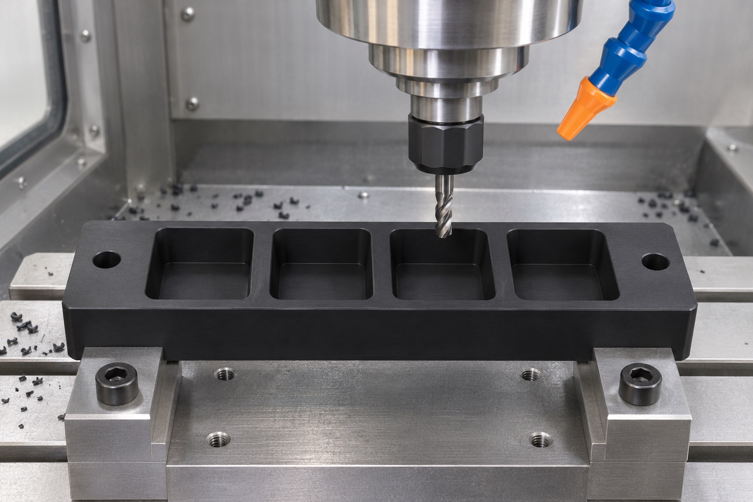
Resolve corner clearance before finishing pockets
Before selecting the final cutter, the review would compare pocket corner radii with the container's external corners and approved contact zones. The proposed route would preserve the intended wall thickness between pockets. Any local relief would be shown on the controlled drawing, not improvised at the machine. If a container did not seat because of a corner conflict, the response would be an engineering review rather than enlarging the whole pocket. The example provides no claimed radius or clearance value because those requirements depend on the identified vessel and its intended support arrangement.
Machine depth and floor geometry to the approved concept
The four blind cavities would be produced to the released depth and floor definition. Chip evacuation and access to the bottom would be considered when planning the operation. The floor would not automatically be treated as the container's vertical locating surface unless the approved design assigned it that role. No drain, side window or fluid passage would be added to the concept. If the application required those features, the design review would address support, remaining material and inspection access before revision. Toolpaths and cutting conditions would be chosen for the actual grade and geometry rather than presented as universal settings.
Maintain the mounting and loading interfaces
The two external mounting holes would remain plain through holes as defined. Inserts, tapped features, counterbores or special screw seats would require an approved change. Their position would be checked against the pocket-row references and the equipment mounting interface. The review would also confirm how a tightening tool reaches the fasteners at the intended assembly stage. Pocket lead-ins would be defined for loading without removing an essential support band. A convenient hand fit would not justify rounding every entry edge or changing the relationship between the container, nest and transfer mechanism.
Inspect in an agreed polymer condition
The proposed inspection plan would identify the required conditioning instructions, support and relevant environmental conditions. It would address opening size, depth, corner shape and the relationship between all four pockets and the mounting pattern. The measurement method would be selected to reach blind features without deforming thin regions. Inspection records would identify sampled characteristics and the actual drawing revision. This representative example contains no measured values and therefore reports no achieved tolerance. A later real report would need actual results and acceptance decisions, not a statement that the carrier looked consistent with its generated illustration.
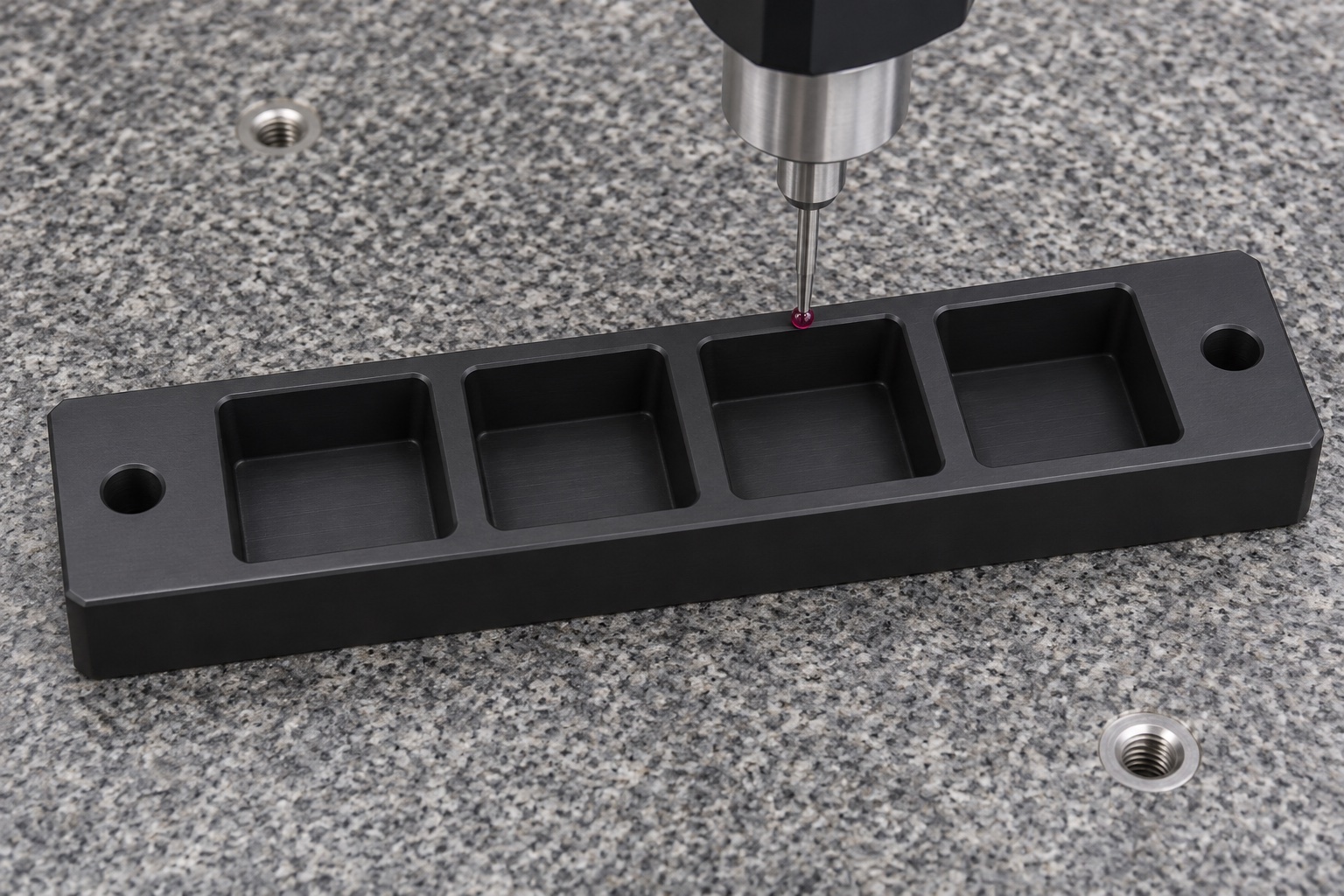
Deburr and clean without changing the pocket envelope
Pocket entries, internal transitions and mounting-hole edges would be reviewed for attached machining material. An approved finishing instruction would preserve the defined contacts and lead-ins. Local scraping to admit a development container would be treated as rework and assessed against revised requirements if authorized. Cleaning would follow the contracted component process and keep machining debris out of the cavities. Visual smoothness would not establish a particle limit or validated decontamination. The proposed traveler would preserve the relationship between material, revision, machining operations and inspection status through any external cleaning or handling steps.
Limit an optional nonclinical handling observation
An agreed development observation could use identified empty containers to examine insertion, orientation, gripper access and removal. The procedure would record the carrier and container revisions and any relevant motion conditions. It would not claim assay validation, clinical safety, contamination control or retention throughout the analyzer's operating envelope. If a container rocked or stuck, the team would review the contact map and corner geometry before modifying the nest. Trial parts would remain identifiable and separate from released production. Any approved change would be incorporated into the drawing, program and inspection requirements before repeat manufacture.
Package without loading the cavity walls
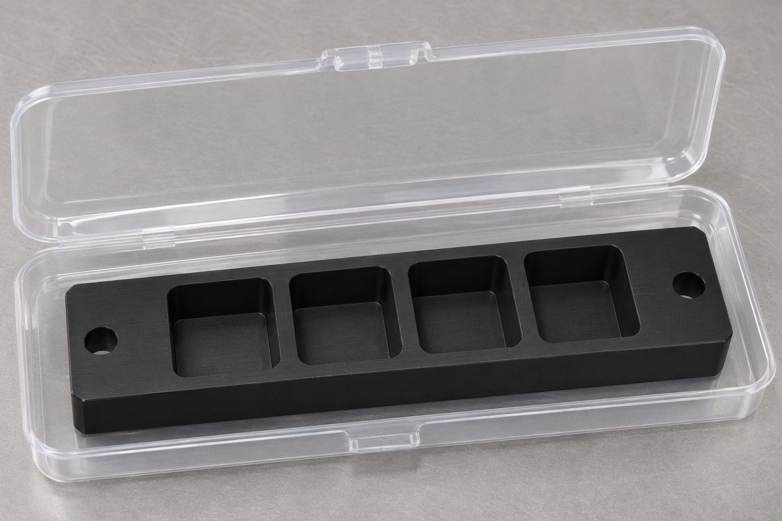
The protective packaging proposal would avoid placing tight inserts or separators inside the four pockets. It would protect the base and pocket entries from other components while allowing the part identity and revision to remain visible on the associated label. Packaging material restrictions would be agreed before selection. The package would not imply sterile delivery or validated cleanroom handling. If the purchaser performed final cleaning, the handover condition would be stated. A used laboratory container would not be shipped as a fit reference unless its condition and handling were explicitly approved for that purpose.
Preserve the container-specific release basis
A repeat-order package would retain the identified vessel, permitted exterior contacts, pocket corner and floor definitions, row references, polymer grade and inspection condition. A new container supplier or revision would trigger review even if the nominal square size appeared unchanged. The example illustrates a traceable manufacturing discussion, not a universal cuvette holder or a validated analyzer accessory. No customer history, production quantity or measured improvement is invented. The responsible equipment team would separately evaluate handling, retention and any measurement role in the real medical laboratory workflow before release for its intended application.
Manufacturer background reference: www.ensingerplastics.com.
FAQ
Is this an actual medical analyzer customer case?
No. It is a representative machining example with a proposed workflow and no fabricated delivery or measurement results. A real project would need approved container data, released drawings, material requirements and inspection evidence before the component could be accepted.
Does the concept include cuvettes or sample-liquid contact?
No. The illustration shows a carrier only. The intended mechanical scope is support of approved external regions of identified closed containers. Direct fluid contact or a measurement-cell role would require a different application assessment and explicitly controlled requirements.
How many pockets and mounting holes are proposed?
There are four square blind pockets in one row and two plain through holes outside the pocket row. No drains, inserts, threads or optical windows are included. Additional features would require review of the contact map, remaining material and manufacturing documents.
Would a container fit check replace dimensional inspection?
No. A fit observation can reveal some interference but does not document the complete pocket profile, depth or pattern location. Use an agreed measurement plan and identified container data, and keep limited development observations separate from formal acceptance of the machined component.
Can the grade be changed to another black polymer?
Only through an authorized material change. Color is not a material identity. The equipment team and supplier would review the effect on the application, dimensional behavior, machining route, inspection and any cleaning or traceability requirements before substitution.
What is explicitly outside the proposed delivery scope?
The example claims no clinical use approval, assay performance, chemical or biological qualification, sterilization result, measured particle level or transport retention capacity. Ordinary protective packaging and a dimensional report would not independently establish any of those system-level results.

tanghangyun@oemach.com