
A robot output-shaft flange transmits torque through a compact set of fitted features. The center bore, stepped diameters, flange face and mounting holes must remain related to one rotation axis after heat treatment and finishing.
For this 45 steel component, OEMach planned machining around a shared center-and-face datum, with finish allowance reserved for distortion after quench and temper. Hardness, runout, fit and black-oxide condition were verified before delivery.
Project Snapshot
| Item | Project detail |
|---|---|
| Application | Torque-transmitting output-shaft flange for a robot joint |
| Material and finish | 45 steel, quenched and tempered to the project requirement of 45 HRC, with black oxide |
| Key features | Center fit bore, stepped outside diameters, flange face, threaded hole group and local relief |
| Control focus | Common rotation axis, radial and face runout, post-heat distortion, hardness, thread quality and corrosion protection |
Define One Rotation Axis Before Machining
The center fit bore, outside steps and flange face determine the running condition of the assembled shaft. Changing datums between operations can create radial runout or face wobble even when each diameter is within size tolerance.
OEMach establishes the center and face references during pre-machining and carries that logic through heat treatment, finishing and inspection. Chamfers and relief grooves are also reviewed because they affect seating against the mating component.
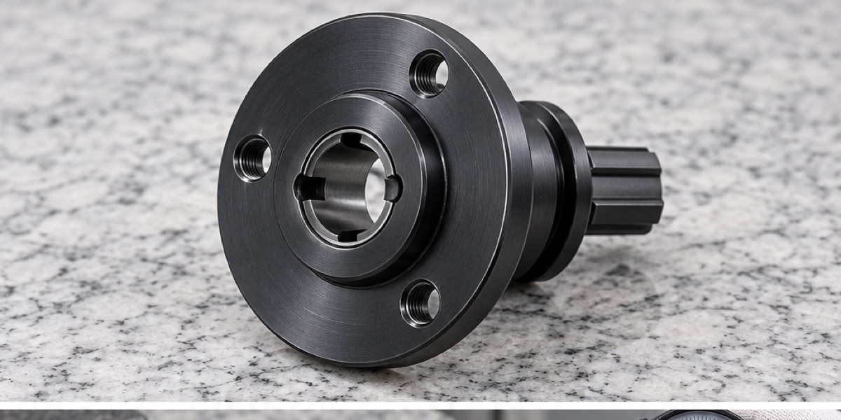
The center fit bore, stepped outside diameters, flange face and threaded hole group form one torque-transmitting interface.
Heat Treatment Changes The Finishing Strategy
The part is rough-machined with controlled allowance before quench and temper. The project requirement is 45 HRC, so hardness and distortion are checked after treatment before the final cutting plan is released.
First-article post-heat data is used to adjust allowance for later batches. Too little stock may leave an unclean finish; too much increases cutting load on hardened material and can affect bore geometry.
Finish Bore, Diameters And Face From A Common Axis
After hardness confirmation, the fit bore, stepped outside diameters and functional face are finished from the same rotational reference wherever practical. This controls concentricity and face runout as assembly characteristics, not isolated measurements.
The face hole group is completed after the rotary features are stable and is related back to the center axis. Threads, chamfers and the local undercut are finished without damaging seating surfaces.
Inspection Connects Hardness With Geometry
Inspection covers the center fit bore, outside steps, face runout, hole position, thread GO and NO-GO gauges, chamfers and hardness records. All results use the same functional datum logic as production.
Before black oxide, the part is cleaned and deburred. After treatment, bore cleanliness, fits, appearance and rust-preventive condition are checked. If 72-hour neutral salt-spray performance is specified, the acceptance criterion and treatment batch record must be confirmed in the order.
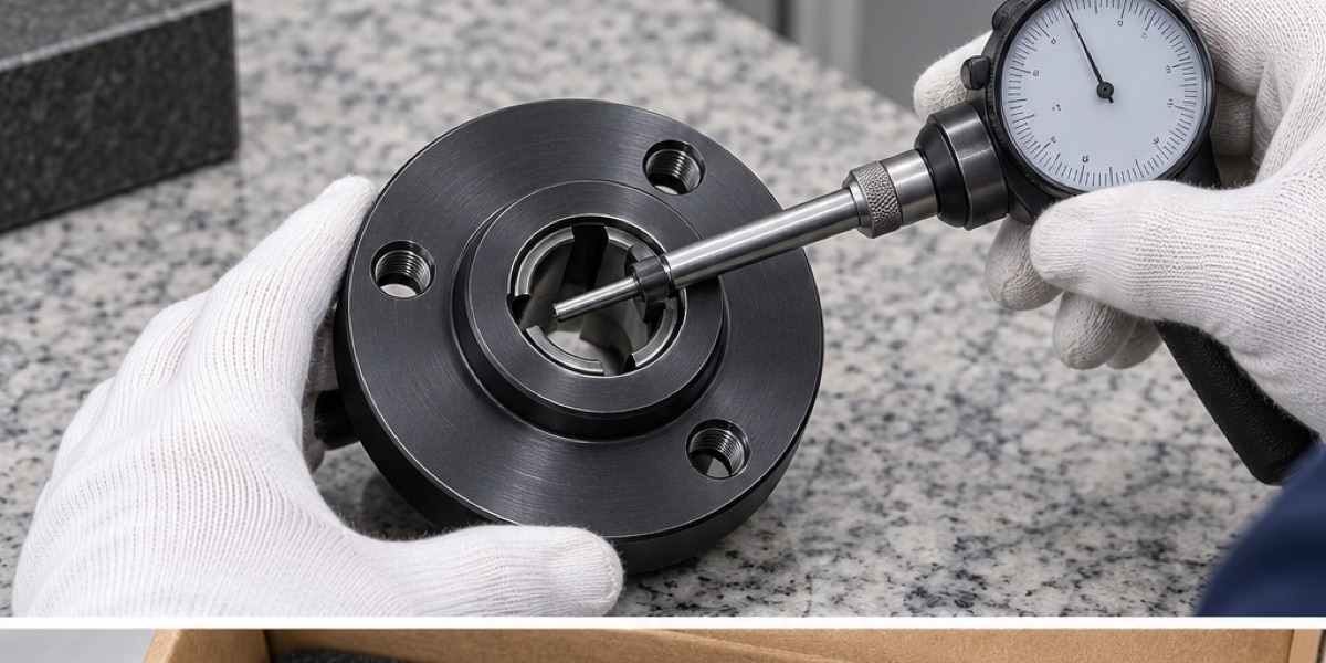
A bore gauge verifies the finished fit after quench-and-temper distortion has been removed by the final machining sequence.
Lead Time And Packaging Protect Precision Steel Parts
A practical reference is 7 to 10 working days for prototypes and 10 to 15 working days for small batches. Heat-treatment certification, expanded reports or corrosion testing may change the confirmed schedule.
Each flange is separated in foam to protect the bore, flange face and black-oxide surface. Rust-prevention material and dryness control are selected according to the expected transport and storage period.
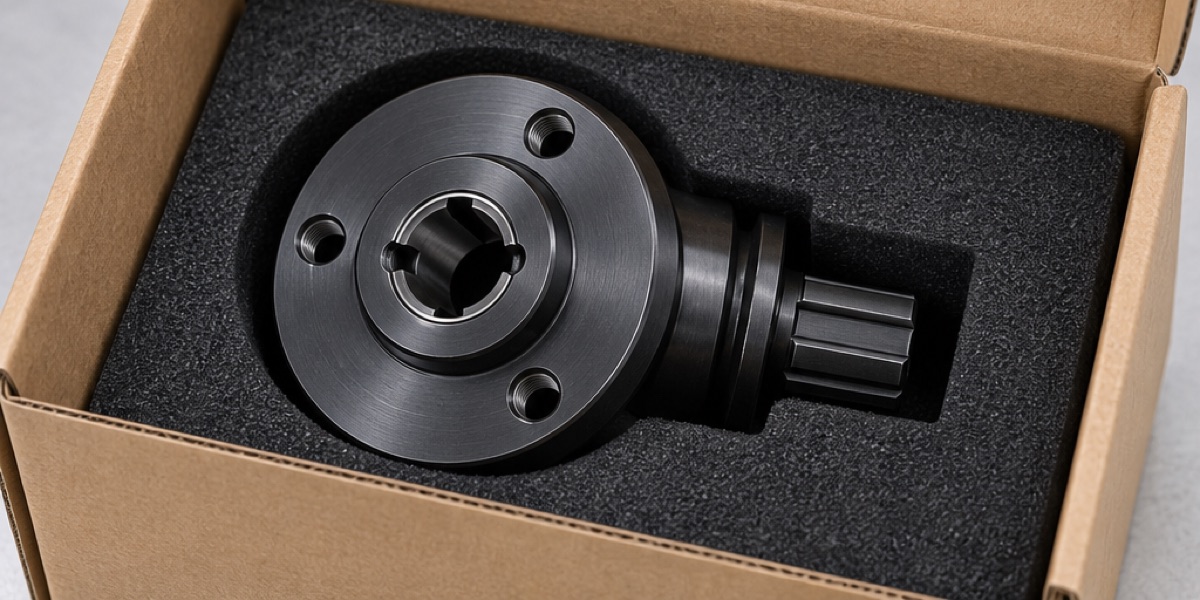
Foam separation protects the bore, flange face and black-oxide surface while rust-prevention measures are matched to storage and transport conditions.
Case Summary
A reliable output-shaft flange requires one datum strategy across pre-machining, heat treatment, finish machining and inspection. Controlling the common rotation axis, 45 HRC condition, black oxide and packaging protects torque transfer and assembly fit.
FAQ
Why is finish stock left before heat treatment?
Quench and temper can change bore size, roundness, diameter and face relationship. Controlled allowance gives the finishing operation enough material to restore the functional geometry.
Why should the bore, outside diameters and face share one axis?
These surfaces locate and rotate together in service. A common axis limits radial runout and face wobble that separate size checks may miss.
Is 45 HRC checked before or after final machining?
Hardness is checked after quench and temper before final finishing, with records linked to the batch. Final geometry is then verified after machining and black oxide as required.
How is black-oxide steel protected from rust in shipping?
Parts are cleaned, dried and separated in foam, with suitable rust-preventive protection selected for the transport route and storage duration.
Ready to get a quote for your CNC machined parts?
Submit your engineering drawings to qiancj@oemach.com. We support prototype sampling and small-batch production with strict tolerance control.