
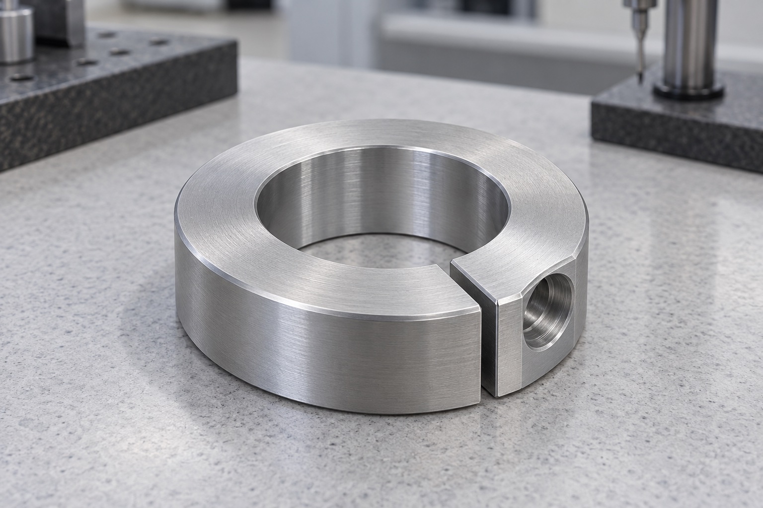
Scope of the representative collar concept
This representative example proposes a one-piece 6061 aluminum split shaft collar for an equipment-side adjustment mechanism in a medical laboratory instrument. The ring has a smooth central through bore, one radial slit and a tangential screw interface. The illustration contains no installed shaft or screw. It describes no actual customer delivery, manufactured sample or measurement record. Achieved tolerance, holding force, slip resistance, vibration endurance, fatigue life, sterile condition and medical certification are not claimed as production results. The proposed route concerns a custom component, not a qualified complete shaft-retention system.

Review the actual shaft and fastener arrangement
A real order would begin with controlled drawing and model, the shaft specification, approved screw and surrounding mechanism revision. The designer would define contact faces, axial location, allowed adjustment and installation access. The supplier would clarify how a one-piece ring reaches the intended shaft region and how a tool reaches the screw after assembly. A visible slit would not authorize forced opening over a shoulder. Missing fit, thread or service requirements would be resolved before route selection. Component manufacture, optional assembly observation and full retention qualification would remain separate deliverables with explicit responsibilities.
Retain approved aluminum evidence
Material records would identify the accepted 6061 condition, stock form, lot and purchased final processing. Blank allowance would follow the actual holding and finishing sequence, not dimensions inferred from the illustration. The supplier would not substitute another silver alloy or transfer a commercial collar's rating to this custom ring. Identity would remain linked through turning, slit machining and packing. Stock documentation would establish material identity within its scope, not gripping force or validated cleaning. Relevant final-component properties and environmental requirements would need separately agreed evidence for the actual design and application.
Establish bore and face references
Initial operations would create the approved outside envelope, bore and face references needed for the later split and screw features. Holding contacts would protect functional surfaces and avoid concealing deformation. Chips would be removed before repositioning. The supplier would preserve reference transfer rather than reset each operation from an unrelated raw edge. Intermediate observations could support process development, but final acceptance would address the specified finished state after relevant treatments. A collar that looks circular only under fixture pressure would not automatically conform to its free-state drawing or become an informal dimensional master.
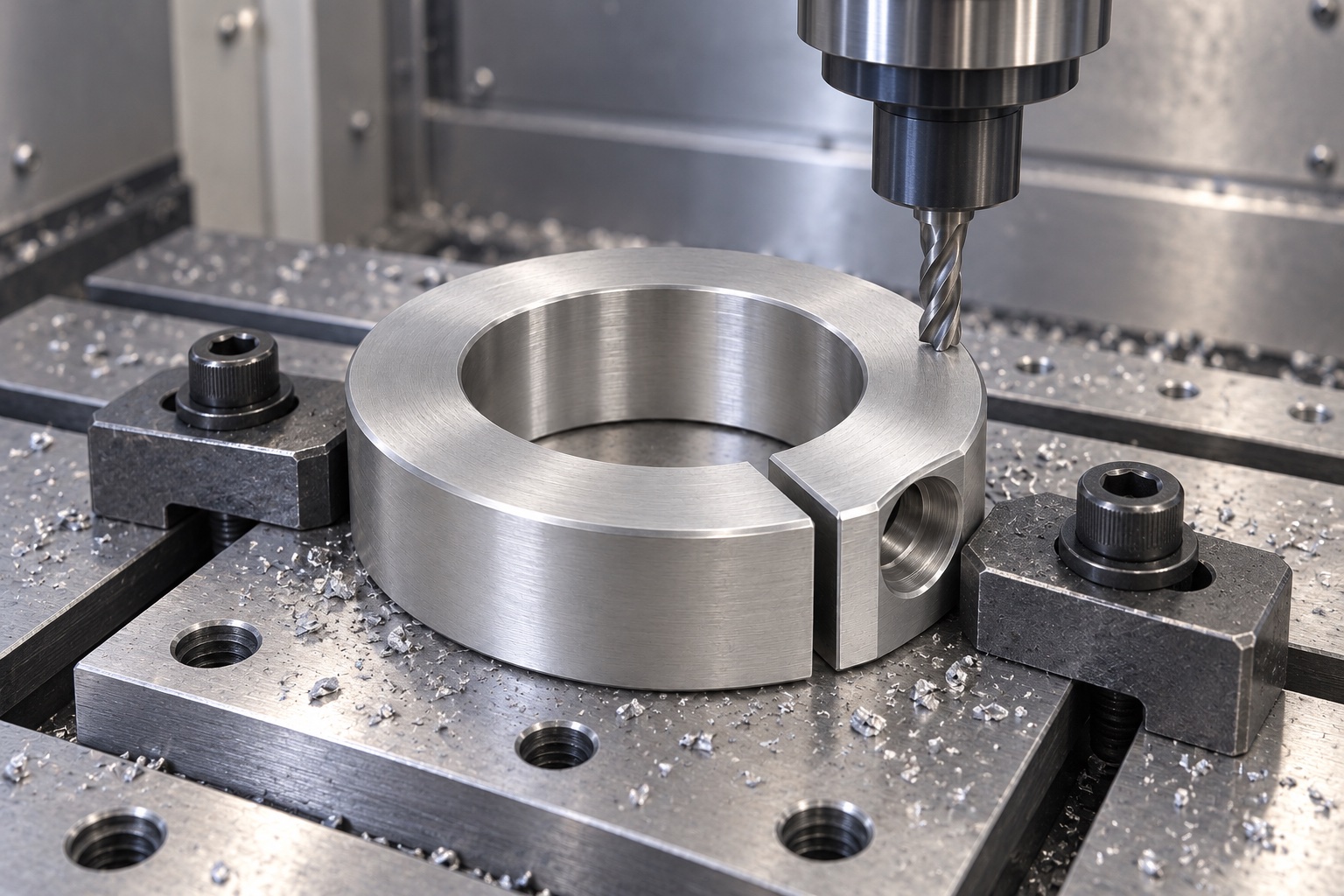
Machine the tangential fastener features
Clearance, counterbore or other approved head seat, mating thread and engagement would follow the actual fastener definition on the two sides of the future slit. The supplier would review tool approach, remaining wall and useful face contacts before finishing. The illustration would not supply a thread size, engagement result or tightening instruction. An unshown insert, locking compound or alternative screw would require design authorization. Drawing and model disagreements would be resolved before final cuts. Approved changes would enter controlled geometry and inspection documents rather than a convenient screw being treated as a universal thread gauge.
Create the controlled radial slit
The slit would follow approved width, location, orientation and edge requirements relative to the bore and screw interface. The machining sequence would account for how the split affects subsequent support and observations. The supplier would not close the gap under force to make a dimension appear acceptable or widen it informally to accommodate an unidentified shaft. Tool access and removal of attached material would be reviewed without changing useful surfaces. Any authorized adjustment would remain traceable in revised geometry and relevant checks. No universal gap, clamping force or achieved dimensional result is provided by this example.
Finish and clean without undocumented fitting
The supplier would examine bore mouths, slit boundaries, face edges and screw-seat transitions for attached material or unwanted sharp features. Approved edge treatment would preserve the useful bore and thread definition. Polishing until one shaft enters would require authorized review rather than disappearing as cosmetic work. Cleaning and final treatment would follow the purchased scope. A smooth bright aluminum surface would not demonstrate measured particles, validated disinfection, biological suitability or sterile delivery. Lot, revision, process state and approved changes would stay linked before final inspection and mechanical protective packing.
Inspect the agreed finished condition
The proposed inspection plan would cover bore, faces, outside envelope, slit and screw features using accessible methods and an explicit support condition. If assembly hardware or a fixture condition were required by the real drawing, those details would be controlled and recorded. A shaft or screw passing into one feature would not verify the full ring. The measuring-machine image illustrates a possible arrangement, not an achieved tolerance. Actual observations in a real order would address the finished component and approved revision, not a constrained appearance accepted solely because a selected demonstration shaft happened to fit.
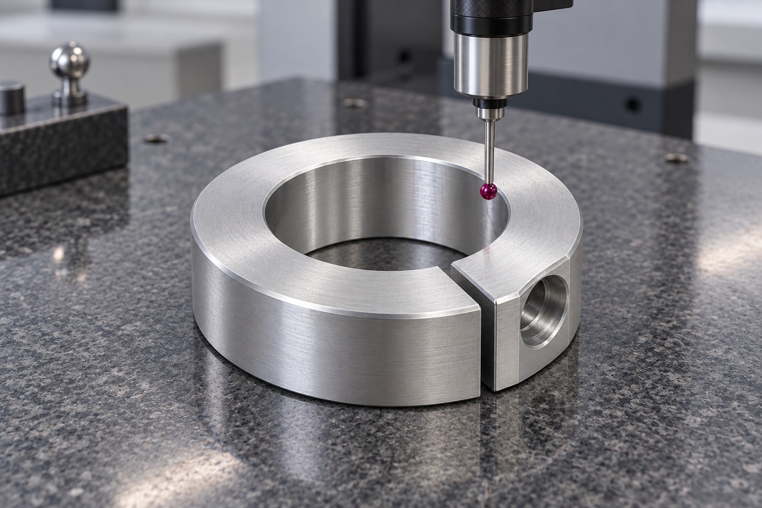
Create records without invented grip results
A proposed first-article report would identify revision, material lot, final condition, numbered characteristics and inspection methods. No measured values are supplied because this representative example has no manufactured specimen or actual inspection dataset. A real project would record observations, discrepancies and authorized changes transparently. A conforming dimensional report would not establish holding force, slip, vibration, fatigue or instrument safety. Optional fitting and full application qualification would remain separately identified work. This prevents an illustrative manufacturing route from becoming invented customer acceptance or a claimed mechanical improvement that was never demonstrated.
Limit an optional installation trial
An agreed observation could examine assembly route, orientation, seating and screw access with identified ring, shaft and fastener revisions. The procedure and test condition would be recorded. Unexpected interference would be reviewed before altering the bore, slit or surrounding hardware. A favorable manual trial would not qualify holding force, resistance to slip, vibration behavior or retention during service. Those properties would require separately defined evaluation of the complete actual mechanism. Trial parts would stay distinct from released production, and approved adjustments would enter controlled documents before another order rather than remain in a forcibly modified sample.
Protect the accepted contact geometry
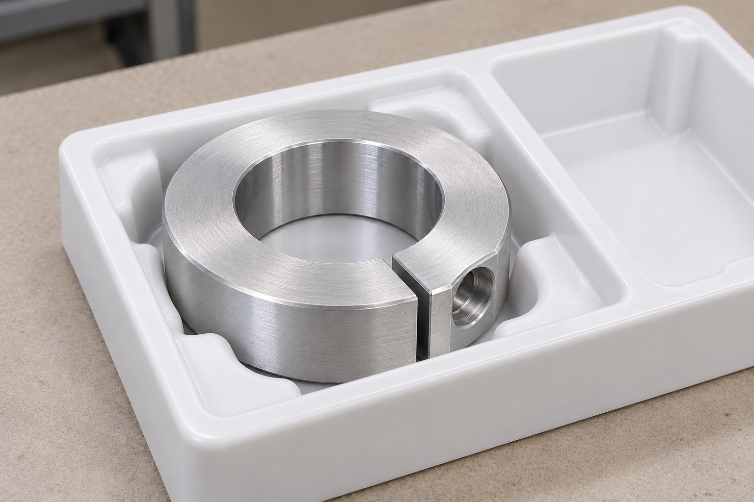
Finished collars would occupy individual pockets or supports that protect the bore, split boundaries and screw seat without squeezing the gap shut. Loose metallic hardware would not strike accepted contacts. Mechanical shipping protection would not mean sterile delivery or validated cleaning. Grade, lot, revision, final process and inspection status would accompany dispatch. Receiving checks would distinguish visually similar rings with different bores, slit definitions, widths or screw features before installation. These measures would preserve accepted component identity while leaving assembly tightening, holding qualification and the full instrument's service evaluation to separately controlled application work.
Preserve a collar-specific production baseline
The final package would retain approved geometry, shaft and screw interfaces, installation route, useful contacts, inspection condition, material evidence, final processes, inspection methods and packaging. Authorized prototype changes would become revised documents before repeat manufacture. Changes to shaft finish, fastener or surrounding instrument would trigger review even if the ring looked unchanged. This representative workflow defines a traceable turning and milling project without inventing customer history, achieved tolerances, tightening values or clamp ratings, and without confusing an accepted split aluminum component with a universally qualified shaft-retention or medical-equipment safety system.
Manufacturer background reference: www.carrlane.com.
FAQ
Does this example describe an actual customer delivery?
No. It is a representative proposed CNC route with illustrative images. No delivered order, manufactured specimen or measured result is described. A real project needs approved documents, material and production records, actual inspection and any separately required application qualification.
Are the shaft and clamp screw supplied in the concept?
No. The illustration concerns the isolated ring. Actual shaft, screw, access and surrounding contacts belong to separately controlled assembly documents. Their selection and performance cannot be inferred from a smooth bore, visible slit or apparently familiar clamp-screw opening.
Does the example provide a holding-force measurement?
No grip, slip or holding-force result is supplied. Dimensional conformity is distinct from the complete assembly's retention performance. Required loads, operating conditions, installation procedure and supporting evaluation must be defined separately for the real instrument, not copied from this illustrative route.
Why is inspection support part of the proposed plan?
A split ring can show a different apparent geometry under external restraint. The plan must identify the drawing's agreed finished condition and suitable supports. Appearance while squeezed in a fixture is not by itself proof of conformity in the required state.
Can an unapproved screw or insert complete a missing interface?
No. Fastener identity, clearance, head seat, mating thread and engagement require an authorized definition. An alternative screw, insert or locking treatment needs revised documents and relevant inspection, rather than silently changing the proposed ring to make a trial assembly work.
What should a further order review?
Review shaft, screw, slit, bore, faces, support condition, material and treatment together with installation access. Incorporate approved changes into controlled revisions. Do not preserve a forcibly opened or polished sample as a universal production master or claim another collar's performance.

tanghangyun@oemach.com