
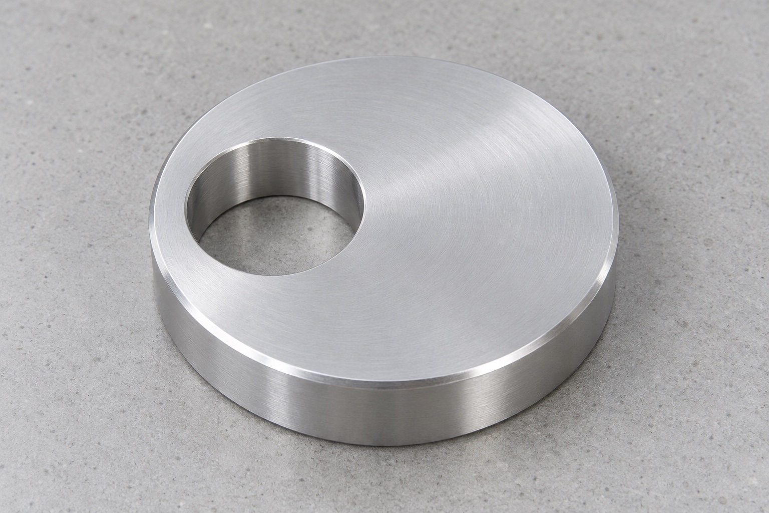
Representative proposed eccentric disc
This representative example proposes a one-piece 6061 aluminum eccentric disc for a service mechanism in medical laboratory equipment. It has a thick flat circular body, one plain off-center through hole, opposing flat faces and restrained edge breaks. No thread, keyway, scale, extra hole or separate retaining component is included in the concept. No actual customer delivery, manufactured sample or measurement dataset is described. Achieved tolerances, adjustment travel, wear life, load, locking behavior, sterile status and medical certification are not claimed as actual production outcomes. The complete mechanism would require its own approved design and application verification.

Review the actual adjustment mechanism
The proposed order would begin with the controlled drawing and model, mounting member, mating contact, support and device revision. The equipment team would define permitted settings, rotation envelope, access and separate holding arrangement. The relationship between the bore and circular exterior would be explicit, not copied from the image. Missing constraints and model conflicts would be resolved before route selection. Component manufacture, optional fitting and complete adjustment qualification would remain separate deliverables. A disc that turned around one convenient rod would not become a universal accepted interface or a demonstration of the medical instrument's operational stability.
Preserve the approved aluminum evidence
Material records would identify the accepted 6061 grade, condition, form, lot and purchased final treatment. Blank allowance would follow the actual holding and finishing plan rather than an assumed universal thickness. Identity would remain associated through turning, offset machining and packing. Silver appearance would not authorize another alloy or a hidden treatment. Material evidence would identify stock within its scope, not prove wear life, load capacity, validated cleaning or sterile delivery. Required surface and environmental properties would need separately agreed evidence for the actual finished component and application rather than values borrowed from a commercial cam or another fixture.
Establish the circular body and face references
Initial operations would create the required exterior and face references according to the released geometry. The supplier would review useful lengths, thickness and future holding for the off-center operation. A convenient raw edge or a strongly clamped appearance would not replace the functional reference. Chips would be removed before reorientation. Intermediate checks could assist route development, but final acceptance would address the agreed delivered condition after relevant operations and purchased processes. Changes affecting the relationship between mounting, faces and useful exterior contact would remain visible in controlled manufacturing and inspection documents.
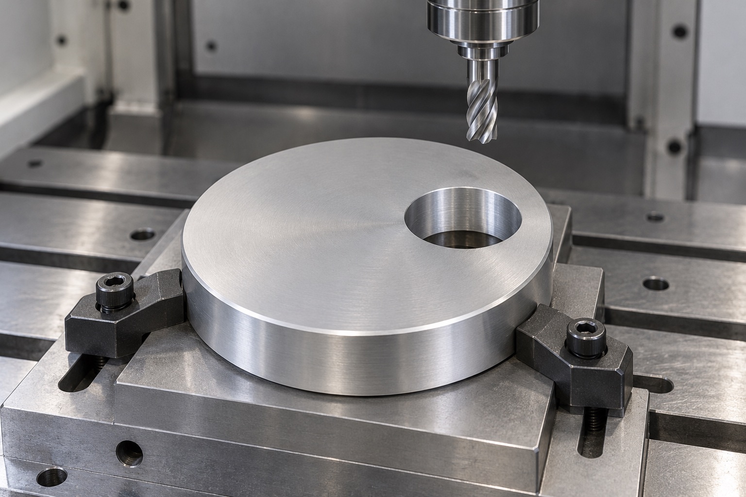
Create the specified off-center through bore
The opening would follow the approved size, location, through depth and entry requirements relative to the accepted axis and face references. Tool access and remaining material near the narrow side would be reviewed before machining. The supplier would not recenter, enlarge or shift the hole to suit an unidentified mounting member. Model and drawing discrepancies would be resolved before the final cut. Any authorized change would enter revised geometry and inspection requirements, preserving the intended eccentric relationship rather than leaving production dependent on a hand-fitted sample or an assumed resemblance to a conventional concentric washer.
Keep useful contact and thickness requirements distinct
The actual design would identify the round contact perimeter, face contacts, finished thickness and required relationships. Permitted chamfers and noncontact areas would remain distinguishable from functional regions. The supplier would not polish away a useful rim or locally reduce thickness to obtain easier movement in one assembly. Such proposals would require design approval and relevant final checks. Purchased treatment effects would remain part of the route. Component conformity would not independently establish contact force, adjustment resolution, preload, retention or safety of the complete mechanism, mounting member and equipment installation under actual operating conditions.
Finish and clean the approved boundaries
The supplier would inspect bore entries, face edges and exterior transitions for attached material or unwanted sharp features. Approved edge breaks would preserve useful contact and the specified offset geometry. Cleaning and final treatment would follow the purchased scope, not infer a finish from the photograph. A smooth bright surface would not prove measured particles, antimicrobial action, validated disinfection or sterile supply. Any approved identification marking would avoid useful contacts and follow its own controlled location. Lot, revision and authorized adjustments would stay linked to the actual disc before dimensional acceptance and mechanical packaging.
Inspect the final relative geometry
The proposed inspection plan would identify methods for the bore, exterior, face contacts, thickness and axis offset. Support, references and final condition would be agreed before acceptance. Separate diameter checks would not verify relative position. A pin fitting in the hole would not replace inspection of the exterior or the complete geometric relationship. An illustrative CMM image would show a possible setup, not an achieved tolerance. Actual observations in a real project would refer to the finished component after relevant processing, not its fixture-constrained appearance or one unidentified mating sample used as an informal dimensional standard.
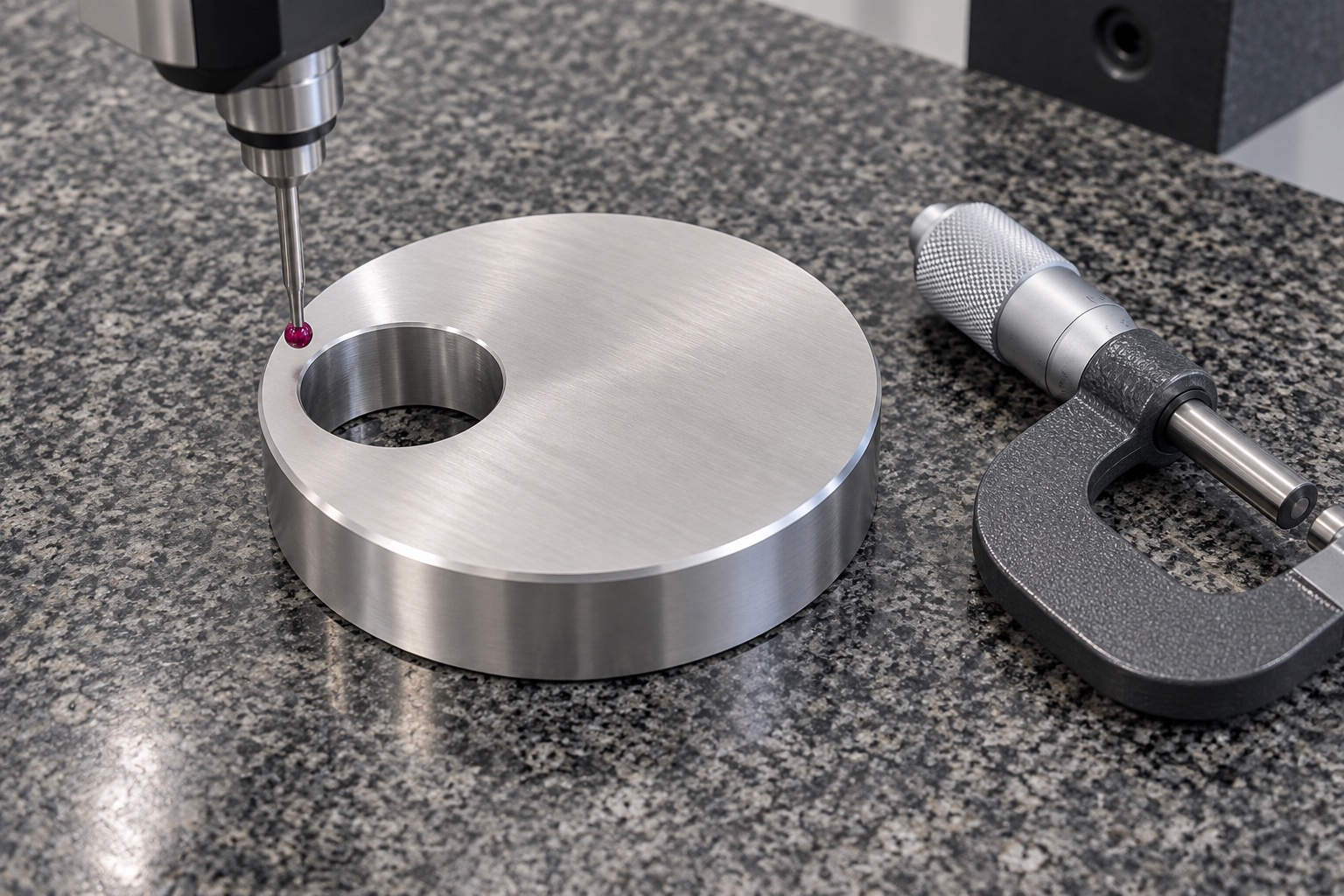
Create records without invented adjustment results
The proposed report would identify revision, material lot, numbered features, methods, final condition and actual observations in a real order. No measurements are supplied because this representative example has no manufactured specimen or inspection dataset. Discrepancies and authorized changes would remain traceable. A conforming dimensional report would not establish useful travel, repeatability, vibration resistance or load capacity of the full device. Optional assembly observation and complete application qualification would remain separate work. This avoids reporting an illustrative manufacturing route as a customer's acceptance, a measured improvement or a qualified medical adjustment result that has not actually been demonstrated.
Limit an optional rotation and contact trial
An agreed trial could observe mounting, seating, permitted rotation, intended contact and access using identified disc, support, member and mechanism revisions. Installed orientation, procedure and separate holding method would be recorded. Unexpected interference or rocking would be reviewed before changing the rim, bore or hardware. Favorable hand adjustment would not qualify load, vibration, wear or positional stability in service. Trial pieces would remain distinct from accepted production. Approved adjustments would enter revised documents before another order rather than leave a polished disc as a universal reference for other contacts, supports or medical instrument adjustment mechanisms.
Protect the perimeter and distinguish similar variants
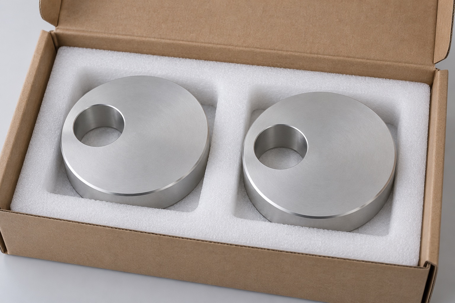
Finished discs would occupy separate supports or pockets that protect useful rims, face contacts and bores without distortion. Loose metal hardware would not strike accepted surfaces. Mechanical transport protection would not imply sterile supply or validated cleaning. Lot, revision, final process and inspection status would accompany shipment. Receiving checks would distinguish visually similar discs with different offsets, diameters, thicknesses or edge treatments before installation. These measures would preserve component identity while leaving full-mechanism holding, motion, wear and service qualification to separately defined application evaluation using the actual instrument and intended conditions.
Maintain an offset-specific production baseline
The production package would preserve released geometry, axis relationship, mounting member, contacts, permitted settings, rotation envelope, retention, material evidence, final processing, inspection and packing. Authorized prototype adjustments would become revised documents before repeated manufacture. Changes to supports, contact surfaces or installation methods would trigger review even when the disc looked similar. This representative workflow defines a traceable custom CNC project without inventing customer history, achieved tolerances, calibration or locking ratings, and without confusing an accepted aluminum eccentric disc with a universally qualified medical equipment positioning, adjustment or service-safety system.
Manufacturer background reference: www.carrlane.com.
FAQ
Is this an actual customer-delivered eccentric disc?
No. It is a representative proposed CNC route with illustrative images. No delivered order, manufactured specimen or measured adjustment result is described. A real project needs approved documents, material and production records, actual dimensional observations and any separately required full-mechanism qualification.
Does the example establish a measured axis offset?
No measured offset or achieved tolerance is supplied. The actual drawing must define the two axes and their relationship, and inspection must verify the finished component using agreed references and methods. An apparently displaced bore in an image is not measurement evidence.
Are mounting and angular locking hardware included?
No. The illustration concerns the isolated disc. Actual mounting members, retainers, clamps or other holding features belong to separately controlled assembly documents. Their selection and performance cannot be inferred from the plain bore, contact rim or a favorable rotation demonstration.
Does easy rotation prove adjustment performance?
No. A hand trial is a limited observation with identified parts and orientation. Useful travel, repeatability, wear, vibration resistance and positional stability need separately defined evaluation of the complete actual mechanism. This representative example claims no such achieved production result.
Can the rim be polished to fit one mechanism?
Not as an undocumented replacement for released geometry. Useful contact, axis offset, diameter and thickness remain controlled requirements. Any adjustment requires authorization, revised documents and appropriate inspection rather than a hand-modified disc becoming the production master for later orders.
What should another order review?
Review the axis relationship, mating contact, mounting and retaining arrangement, rotation envelope, faces, grade and final process. Incorporate approved prototype changes into controlled revisions, not an altered sample or a performance claim copied from another medical equipment adjustment assembly.

tanghangyun@oemach.com