
A robot arm adapter flange may be thin, but its assembly performance depends on the relationship between the center bore, end face, M3 threaded circle and outer mounting pattern. Controlling those features separately is not enough.
For this 6061-T6 project, OEMach organized machining and inspection around the functional center axis and mounting face. Thread quality, hole-pattern clocking, anodizing protection and transport support were included in the same delivery plan.
Project Snapshot
| Item | Project detail |
|---|---|
| Application | Adapter flange for a robot arm joint connection |
| Material and finish | 6061-T6 aluminum with matte silver anodizing |
| Key features | Thin disc, center bore, stepped face, M3 threaded hole circle and outer mounting holes |
| Control focus | Face stability, bore and hole-pattern relationship, thread gauges, edge condition, coating protection and appearance |
Start With The Hole-Pattern Function
The center bore normally establishes the primary location, while the threaded and outer hole circles connect components on opposite sides. Their relative angle and position determine whether the arm module can be assembled without forcing the fasteners.
Before programming, OEMach confirms which bore or face locates the mating part and which feature controls rotational clocking. This keeps the process focused on the assembly relationship rather than isolated dimensions.
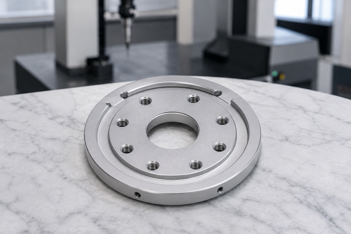
The center bore, stepped faces, M3 threaded hole circle and outer mounting pattern must remain related to one functional datum system.
Thin-Disc Clamping And Small Threads Carry The Risk
A thin flange can deflect under excessive clamping and spring back after release. Dense M3 holes add risks from incorrect tap-drill size, chip packing, oversized chamfers and burrs at the thread mouth.
Matte silver anodizing also makes scratches and color inconsistency visible. Close-fit regions and threads may need coating allowance or protection so the final surface does not interfere with assembly.
Finish The Bore And Hole Circles From A Shared Datum
The route first stabilizes both faces and the center reference, then roughs the disc with allowance for stress redistribution. The center bore, critical step and M3 pattern are finished from the same controlled datum chain wherever practical.
Stable drilling and tapping parameters, reliable chip evacuation and restrained entry chamfers protect the small threads. The outer hole pattern is related back to the center instead of being treated as an independent setup.
Inspection Must Include Fastening Feel
First-article inspection covers the center bore, face condition, M3 GO and NO-GO gauges, outer-hole position, chamfers and the angular relationship between patterns. A coordinate measurement confirms the geometry that determines alignment.
After anodizing, OEMach rechecks thread passage, hole cleanliness, protected fits and cosmetic condition. If a project requires 72-hour neutral salt-spray verification, the acceptance criterion and test time are included in the confirmed schedule.
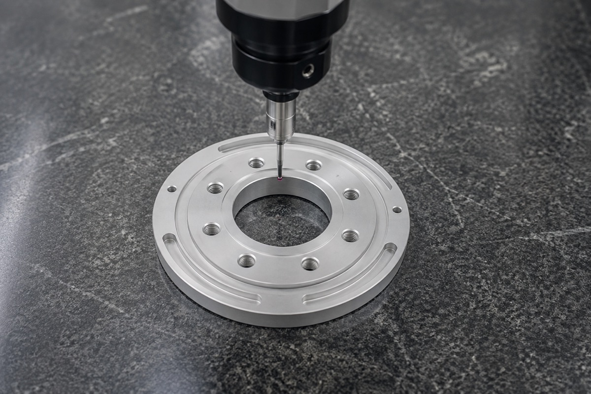
The probing strategy checks the angular and positional relationship between the center axis, threaded holes and outer mounting features.
Lead Time And Packaging Preserve The Thin Flange
A practical reference is 5 to 8 working days for prototypes and 8 to 12 working days for small batches. Full inspection reports, coating masks or corrosion tests can change the final schedule and should be agreed at quotation.
Each flange is supported individually in foam so the disc is not bent and the finished faces do not rub against hard packaging. Hole edges and the matte silver surface remain protected through shipment and incoming inspection.
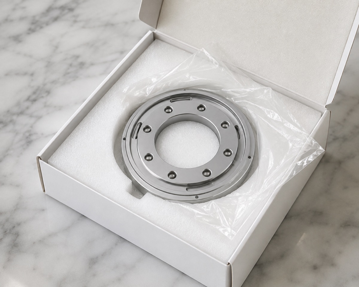
Foam support keeps the faces, hole edges and matte silver finish away from pressure and abrasion during transport.
Case Summary
This case shows that the center bore, M3 threaded circle, outer mounting pattern and end face must be controlled as one assembly interface. Shared-datum machining, post-anodize verification and individual packaging reduce uncertainty at the robot arm assembly stage.
FAQ
Which features should define the flange datum system?
The mounting face and center axis commonly form the primary system, with one hole or clocking feature controlling rotation. The drawing and mating design should confirm the final choice.
Why inspect the M3 threads after anodizing?
Coating residue or contamination can increase insertion resistance even when the threads passed before finishing. Post-finish GO and NO-GO checks confirm usable thread condition.
Can the center bore and outer hole circle be machined in different setups?
They can, but datum transfer must be controlled. Completing critical relationships from one setup or a repeatable shared datum reduces accumulated position and angle error.
How is the thin flange protected during delivery?
Individual foam supports the part without loading the disc and keeps the faces, hole edges and anodized surface away from rubbing or hard contact.
Ready to get a quote for your CNC machined parts?
Submit your engineering drawings to qiancj@oemach.com. We support prototype sampling and small-batch production with strict tolerance control.