
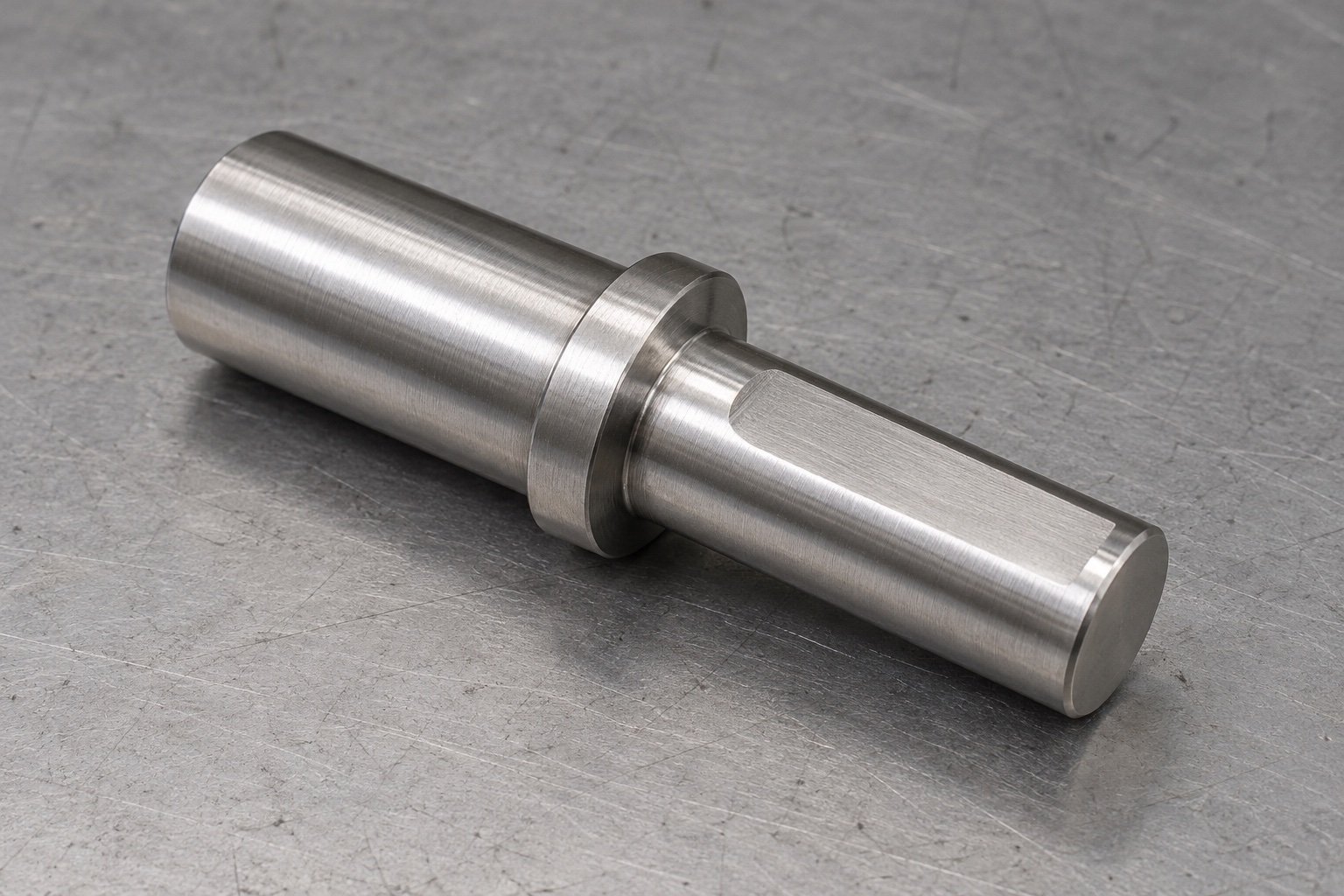
Representative proposed stepped adapter shaft
This representative example describes a proposed one-piece 316L stainless steel adapter for a motor-driven module inside medical laboratory equipment. The solid concept has a larger cylindrical journal, integral annular shoulder and smaller extension with one longitudinal milled flat. It has no thread, keyway, cross hole, gear or separate retaining ring. No actual customer delivery, manufactured sample or measured inspection record is described. Achieved tolerances, torque transfer, axial retention, fatigue life, backlash, sterile status, medical certification and validated equipment safety are not presented as actual measured results of this illustrative turning and milling workflow.

Review both sides of the drive connection
The proposed project would begin with the released shaft model and drawing, actual mating hub or coupling, support, fasteners and installation revision. The supplier would clarify useful journal contact, shoulder seating, flat engagement and any separately defined retention arrangement. A similar commercial motor installation would not approve the custom adapter. Missing dimensions or conflicting interfaces would be resolved before selecting a route. A flat visible in a concept image would not authorize a set screw, clamp or universal installation torque. The equipment team would remain responsible for defining and qualifying the actual complete drive arrangement and service conditions.
Preserve the approved stainless stock
Material evidence would identify the accepted 316L stock form, condition, lot and purchased final processes. Blanks would retain traceable identity as they moved from turning to milling and inspection. Holding allowance and stock preparation would be selected for the actual component rather than prescribed by a generic illustration. Another alloy would not be substituted because it looked similar or was available in a convenient diameter. Material documentation would identify stock within its scope, not prove wear life, galling behavior, corrosion performance or sterile supply. Relevant application properties would need separately agreed requirements and actual supporting evidence.
Turn related diameters and shoulder contacts
Initial operations would establish the approved journals, shoulder face and reference relationships. The route would consider useful lengths, permitted relief and later holding for the flat operation. A rough stock surface would not silently replace the functional measurement reference. Intermediate checks could support process development, but final acceptance would apply after relevant operations and purchased final processing. The supplier would not shorten the shoulder or reduce one journal to accommodate an unidentified hub. Approved adjustments would remain traceable in the model, drawing and inspection plan rather than disappear as an informal fitting step within the machining sequence.
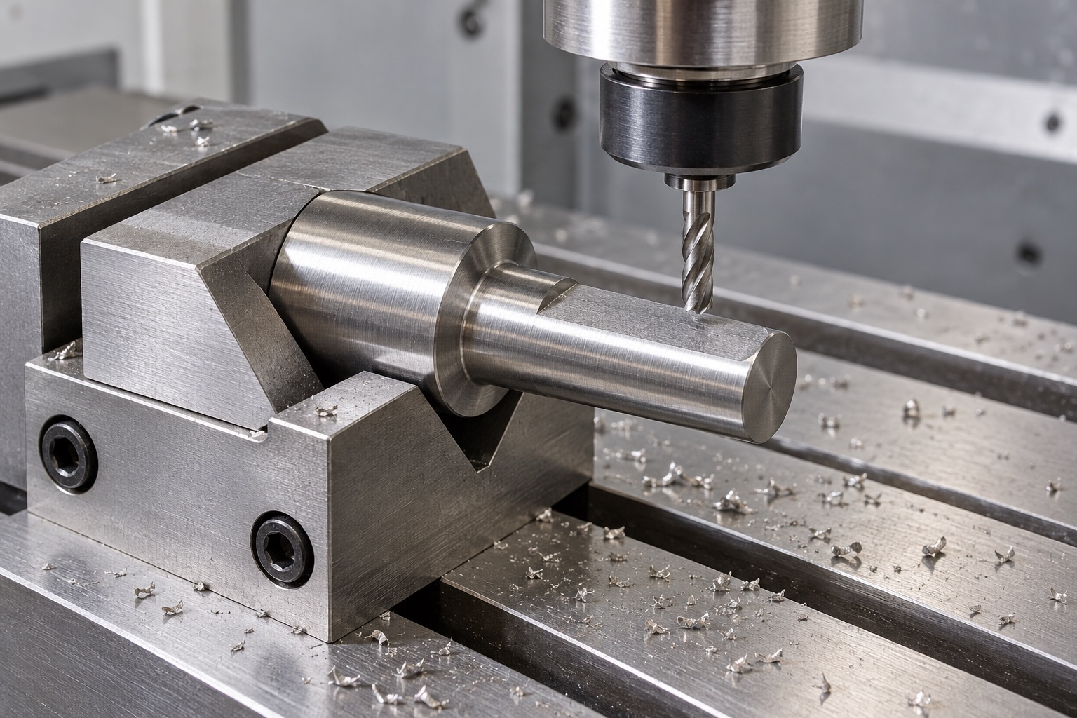
Transfer references into the milling setup
The turned component would be located for milling using suitable protected contacts, with chips removed before reorientation. Support and projection would be reviewed against the actual section and required access. The process would preserve the flat's relationship to the accepted axis and shoulder rather than simply mill a visually horizontal surface. No universal clamping force, tool diameter or cutting setting is supplied in this representative example. If a setup change affected the defined final geometry or inspection references, it would be reviewed before acceptance instead of relying on one favorable fixture-held reading as the complete manufacturing evidence.
Mill the one defined D-profile flat
Flat depth or remaining section, useful length and both transitions would follow the released drawing. Whether the flat ended before or at the end face would be explicit. The supplier would not add a second flat, slot or cross hole to fit another available coupling. Tool access and residual material would be reviewed before completing the final surface. The concept would remain a specific geometry, not evidence of a torque rating. Any required angular relationship to another feature would be inspected through agreed references rather than inferred from the illustration's orientation on a bench or machine table.
Finish transitions without changing useful contacts
Finishing would examine flat boundaries, journal ends, shoulder edges and permitted relief for attached material or unwanted sharp features. Approved edge requirements would preserve useful engagement length, remaining section and shoulder contact. Polishing until an unidentified hub moved freely would require controlled review rather than replace the drawing. Cleaning and final processing would follow the purchased scope with relevant finished-state checks. A smooth stainless surface would not establish measured particle limits, retention performance or sterile supply. Material lot, revision and any authorized adjustment would remain linked to the actual component before final dimensional acceptance and protective packing.
Inspect journals, shoulder and flat together
The proposed plan would identify methods for journal requirements, reference axis, useful shoulder face, axial locations and flat geometry. Support, contacts and final condition would be explicit. Selected micrometer readings would not verify the flat length, transitions or every geometric relationship. An illustrative height-gauge setup would not be reported as an achieved tolerance. Inaccessible features would be discussed before acceptance. The real inspection report would record actual observations against numbered drawing characteristics after relevant operations, retaining the relationship between turned and milled features instead of treating each convenient size reading as an independent substitute for the complete adapter requirements.
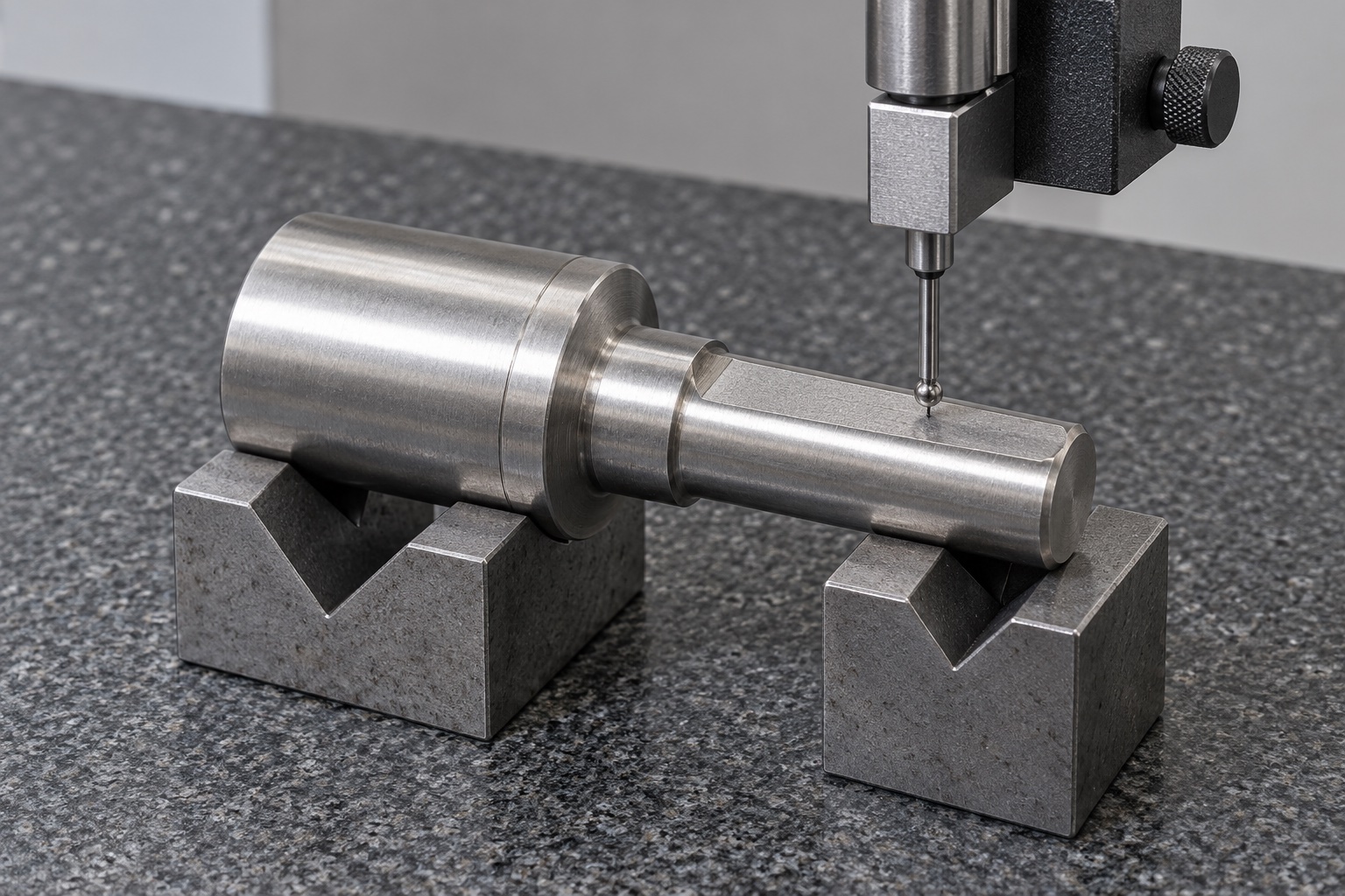
Prepare first-part records without invented performance
The proposed first-part package would identify drawing revision, material lot, final processing, numbered characteristics and agreed methods. No dimensional values or drive results are supplied because there is no manufactured sample or measurement record in this representative case. A real project would record discrepancies and authorized changes transparently. Component dimensional conformity would not establish torque capacity, loosening resistance, axial retention or fatigue life. Optional assembly observations and complete drive qualification would remain separate deliverables. This prevents a plausible process illustration from becoming unsupported customer history, a fabricated acceptance report or a claim of medical equipment safety that has not been verified.
Limit any optional hub-fitting observation
An agreed trial could examine entry, shoulder seating, flat engagement, fastener access and expected movement with identified shaft, hub, support and hardware revisions. The actual installation method and any approved lubricant or retention element would be recorded. Unexpected interference would be reviewed before changing the shaft or mating hardware. Favorable hand fitting would not qualify transmitted torque, pullout, vibration resistance, backlash or medical equipment safety. Trial parts would remain separate from accepted production. Approved adjustments would enter revised documents rather than allow a hand-filed flat or substituted screw to become the reference for a later drive configuration.
Pack useful shaft surfaces separately
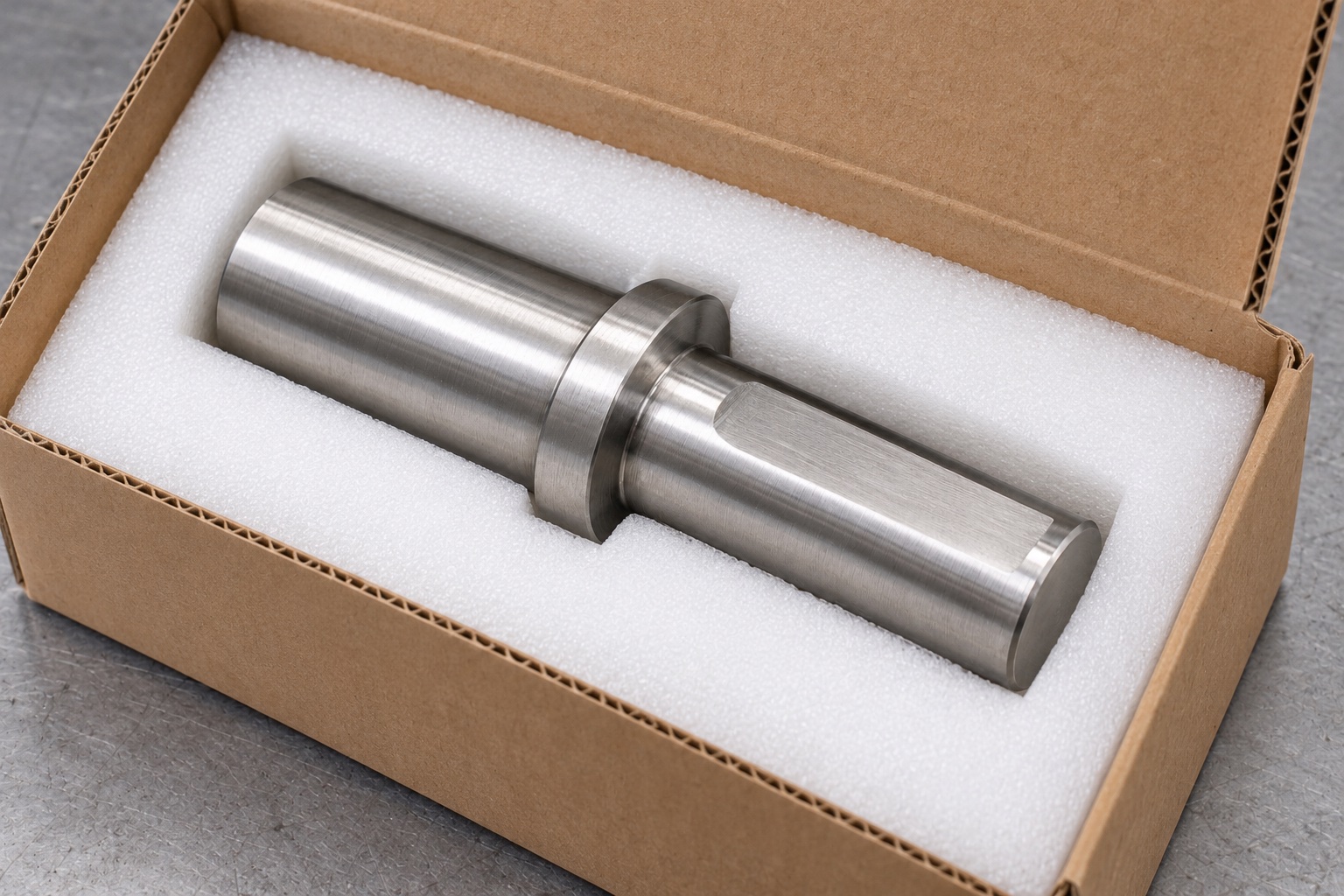
Finished adapters would be separated in appropriately sized pockets or sleeves so metal parts could not strike journals, shoulders or flat edges. Supports and restraint would avoid uncontrolled bending or abrasive contact. Loose fasteners would not share unprotected contact with accepted surfaces. Mechanical transit protection would not imply sterile delivery. Lot, revision, final treatment and inspection status would accompany the shipment. Receiving checks would distinguish similar stepped adapters with changed flat geometry, journal sizes or useful lengths before installation and any separate torque, retention, environmental or maintenance evaluations by the actual medical laboratory equipment team.
Retain a mating-specific production baseline
The final package would preserve released geometry, both mating drive interfaces, support and fastening arrangement, useful contact areas, flat definition, material evidence, final condition, inspection methods and packing scope. Approved prototype changes would become revised documents before repeat manufacture. Changes to hubs, clamps, fasteners, lubrication, supports or service conditions would trigger review. This representative workflow outlines a traceable custom turning and milling project without inventing customer delivery, measured strength or installation approval, and without confusing a conforming D-profile stainless adapter with a qualified complete medical equipment transmission or a universal drive interface for unrelated motor configurations.
Manufacturer background reference: www.orientalmotor.com.
FAQ
Is this an actual customer-delivered shaft?
No. It is a representative proposed manufacturing example with illustrative images. There is no customer delivery, manufactured specimen, measured dimensional report or achieved torque result. A real order would require its own released documents and acceptance evidence.
Does the case specify a drive torque?
No. No drive rating, installation torque or measured retention result is provided. The actual equipment team would define and qualify the complete shaft, hub, support, fastening and operating arrangement rather than infer a value from material identity or appearance.
Why is there only one longitudinal flat?
That is the proposed geometry. A second flat, keyway, hole or thread would be a different feature and would require authorization. The supplier should not alter the interface merely to fit an unidentified available coupling or fastener.
Does a passing diameter measurement verify the flat?
No. Journal checks and flat checks address different characteristics. Useful length, depth, transitions, shoulder relationships and any required orientation need agreed methods and references in the actual finished component condition.
Can this example's material choice prove wear life?
No. The 316L identity alone does not establish wear, galling resistance, fatigue or torque-transfer performance of the complete installation. Any such application requirement needs separately defined conditions and relevant supporting evaluation.
What would be reviewed before another order?
Review mating hub, support, flat geometry, journal and shoulder requirements, fastening, retention, material, final process and operating conditions. Approved adjustments belong in controlled revisions rather than a manually fitted sample or performance data transferred from another drive.

tanghangyun@oemach.com