
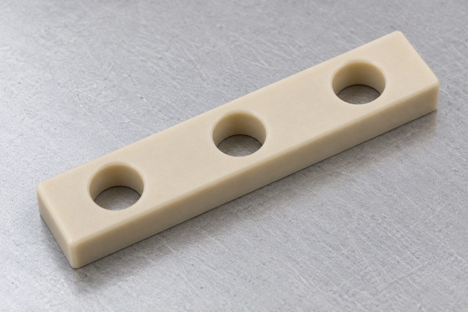
Representative proposed three-hole PEEK bar
This representative example describes a proposed natural unfilled PEEK rectangular spacer bar beneath a terminal arrangement inside medical equipment. Its concept has three equal plain through holes in one row, uniform nominal thickness and flat opposing contact faces. No terminal, conductor, screw or metal insert is part of the illustrated item. No actual customer delivery or manufactured sample is described. Achieved tolerances, dielectric strength, flammability classification, insulation coordination, long-term loading results, sterile status, medical certification and validated equipment safety are not claimed as actual measured outcomes of this proposed CNC manufacturing sequence.

Review the actual mechanical and electrical boundaries
The proposed order would start with the released bar model and drawing, terminal arrangement, support panel, actual fasteners and installation revision. The supplier would identify required stand-off, useful support areas, hole access and any separately defined barrier or insert. Missing information would be clarified before machining. Matching three screws would not establish the correct electrical installation. Mechanical manufacturing and dimensional inspection would remain distinct from the equipment team's electrical and environmental qualification. The supplier would not select safety distances, test voltages or conductor arrangements simply because the component material was described as PEEK.
Retain exact unfilled PEEK stock identity
Material records would identify the approved natural unfilled grade, stock form, lot and purchased conditioning. The supplier would not substitute a reinforced, conductive or other modified PEEK material based on availability or visual similarity. Ensinger's PEEK machining overview would be background on machining and material variants, not certification of this proposed bar. Blank allowance and holding strategy would be reviewed against the actual geometry. Material identity would remain traceable through processing and packing. Any application property beyond the supplied material evidence would require its own agreed acceptance requirement and actual supporting data on a real order.
Establish supported machining references
Initial operations would establish faces and references for the bar thickness, outer profile and hole row. Support would account for the elongated shape and avoid accepting the component only while the fixture forced it into position. Holding contacts would be kept free of chips and would protect future useful faces. Setup changes would preserve reference relationships rather than reset every feature from a convenient raw edge. The actual route, tools and any conditioning step would be chosen for the approved grade and geometry. No universal cutting settings or treatment temperatures are invented by this representative workflow.
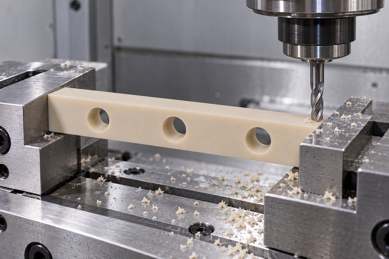
Machine the released support faces
Useful top and bottom contacts, thickness and required relationships would follow the approved drawing. The supplier would distinguish functional lands from permitted edge breaks and noncontact regions. Material removal would be planned so finishing and release from the fixture could be evaluated in the agreed condition. A bar that appeared flat only when tightly held would not automatically pass final acceptance. The supplier would not reduce thickness at one end to fit a changed terminal stack without authorization. Approved changes would remain visible in revised geometry, inspection characteristics and assembly documents for any subsequent production order.
Produce the three plain through holes
Hole type, size, row spacing and location relative to useful faces would follow the released requirements. Drilling and any finishing operations would preserve the approved geometry at both entries and exits. Threaded inserts, counterbores or open slots would not be added for convenience. The actual hardware would determine any separately approved installation access. A pin fitting one bore would not verify the complete row or support-face relationships. If terminal or panel revisions changed the pattern, the supplier would request controlled review rather than manually stretch one hole to obtain a favorable assembly observation.
Finish without obscuring the accepted geometry
The supplier would examine bore exits, long edges, ends and face transitions for attached material or unwanted sharp features. Released edge breaks would preserve useful contact and the specified hole pattern. Polishing would not conceal a positional issue or erase the identity of an accepted reference. Cleaning would follow the purchased scope and protect the exact material grade. The finished ivory appearance would not establish dielectric strength, measured particle limits, sterile supply or validated cleaning. Records would preserve any authorized adjustment before final inspection rather than rely on an informal hand-fitted sample as the accepted production baseline.
Inspect the polymer in the agreed condition
The dimensional plan would identify methods for thickness, useful faces, outside profile, bore size, row position and required relationships. Measurement support, contacts and environmental condition would be agreed before acceptance. The supplier would avoid interpreting a favorable compressed reading as proof of the released component. Gauge and caliper observations would be limited to their actual specified characteristics. Relevant purchased conditioning or final processing would precede final checks where required. An inspection image would illustrate a method only; the actual first-part report would need observations from the real finished bar and its controlled drawing revision.
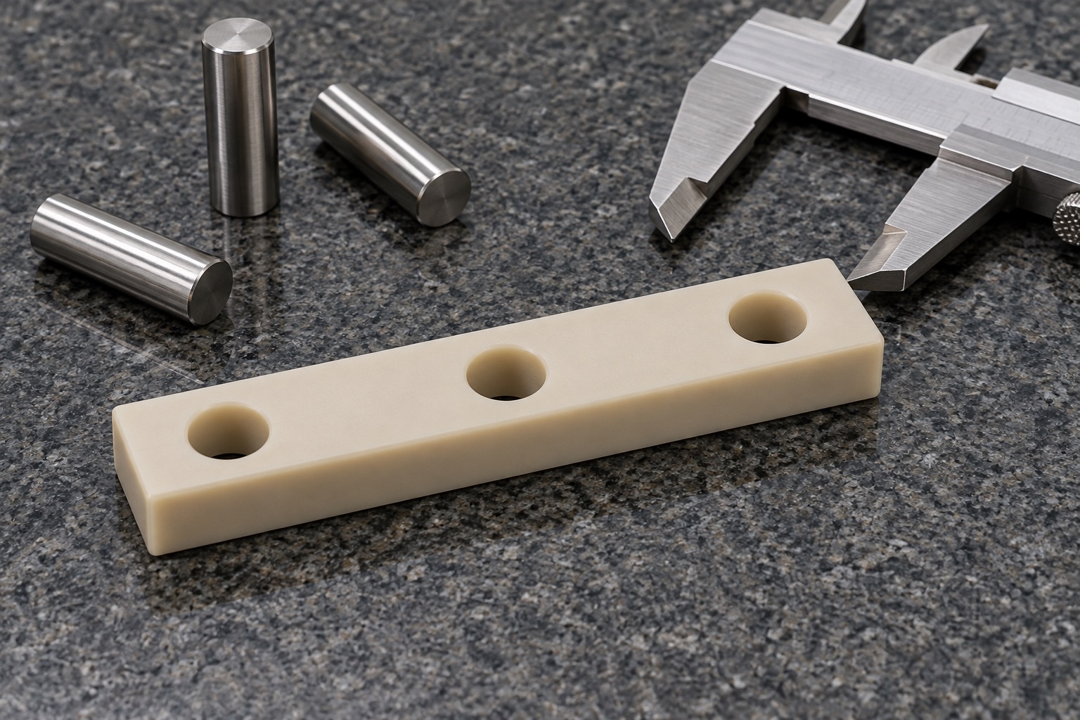
Keep proposed records separate from actual results
The proposed first-part package would identify material lot, grade, drawing revision, numbered characteristics, methods and final condition. No values are supplied because the representative example has no manufactured component or measurement record. Real discrepancies and authorized changes would remain traceable. A dimensional report would not establish insulation coordination, dielectric performance, flammability or medical electrical safety. Optional assembly observations and system qualification would remain separately identified responsibilities. This keeps a useful manufacturing example from becoming a fabricated customer success story or an unsupported claim that a visually simple PEEK bar already meets a finished medical device's electrical requirements.
Bound any terminal-stack fitting observation
An agreed trial could observe stand-off, seating, screw entry and terminal alignment using identified bar, terminal, panel and hardware revisions. Any approved washers, barriers or inserts and the installation method would be recorded. Unexpected interference or bowing would be reviewed before changing the polymer. Successful mechanical fitting would not qualify electrical separation, temperature behavior, long-term deformation or safety of the installation. Trial pieces would remain separate from accepted production. Approved adjustments would enter revised documents rather than make a manually drilled bar the reference for another terminal family or changed medical equipment electrical compartment.
Protect faces and material identity in transit
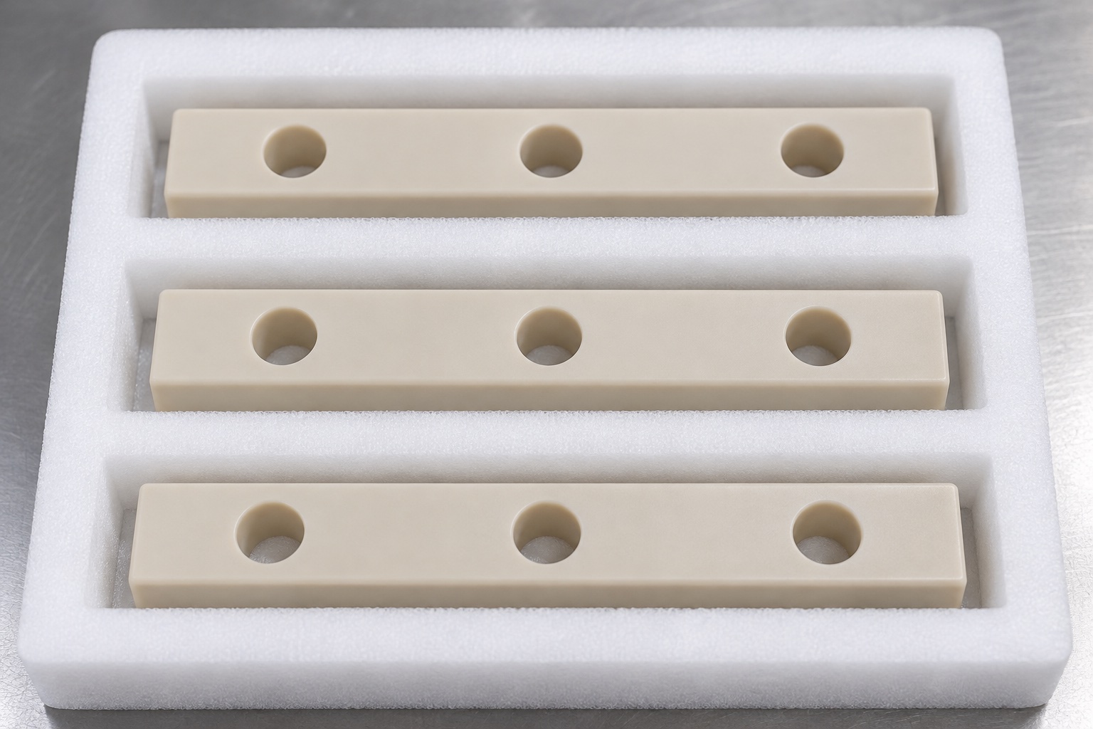
Finished bars would occupy individual pockets or sleeves sized to avoid bending the long section. Loose metal parts would be separated so they could not strike bores or become embedded in useful contacts. Mechanical protection would not imply sterile delivery or a validated electrical property. Material grade, lot, revision and inspection status would accompany the shipment. Receiving staff would distinguish similar ivory bars with different pitch, thickness or material modification before installation. These controls would preserve the accepted component condition while leaving complete terminal assembly, electrical and environmental qualification to separately agreed application evaluations.
Preserve a grade-specific repeat-order package
The production baseline would include released geometry, exact PEEK stock identity, terminal and panel interfaces, actual fasteners, useful contacts, hole-row requirements, final condition, inspection methods and packing scope. Approved prototype changes would be incorporated before repeated manufacture. Changes to terminal pitch, hardware, material modification or service environment would trigger review even if the outside profile remained similar. This representative workflow outlines a traceable custom CNC project without inventing customer history, measured tolerances or electrical approval, and without confusing a conforming mechanical spacer with a qualified protective component in a complete medical equipment electrical installation.
Manufacturer background reference: www.ensingerplastics.com.
FAQ
Is this an actual delivered terminal spacer?
No. It is a representative proposed CNC workflow with illustrative pictures. There is no customer delivery, manufactured sample or achieved test result. A real project would require its own approved documents, material evidence, production records and measured acceptance report.
Does the case include conductors or metal inserts?
No. The concept is a one-piece unfilled PEEK bar with three plain through holes. Terminals, screws, conductors, inserts and barriers belong to separately defined assembly documents. They must not be inferred from this isolated component example.
Is a dielectric test result available?
No. No electrical test result is presented. The equipment team would define and qualify the real installation, including conductive parts, fasteners, exact material, geometry and environment. Component dimensional acceptance does not independently establish a protective electrical function.
Why retain the exact material grade?
The general PEEK name includes materially different variants. The approved unfilled grade, stock and lot evidence need traceability. Similar color or a supplier's general machining description does not authorize substitution or transfer qualification to the finished terminal installation.
Does a pin fitting each hole verify the full bar?
No. It addresses selected bore characteristics within the agreed method. Hole-row position, thickness, useful faces and required geometric relationships need their own inspection scope in the defined final component condition.
What would another production order review?
Review exact grade, terminal and panel revisions, hardware, stand-off, contacts, hole row, final condition and service environment. Approved changes must enter controlled documents rather than remain in a manually modified prototype or an unsupported electrical acceptance assumption.

tanghangyun@oemach.com